00198320-02_UM_ShuttleExtension-DE-EN-ZH.pdf - 第185页
Assembly and Instruction Manual 7 Barcode reader extension Shuttle Extension Edition 11/2018 7.4 Assembly Instruction 87 7.4.13 Step 13 Remove SIPLACE TX machi ne cover of Box PC (1) Install PCIe LAN card 03118 416- …
7 Barcode reader extension Assembly and Instruction Manual
7.4 Assembly Instruction Shuttle Extension Edition 11/2018
86
7.4.12 Step 12
7
7
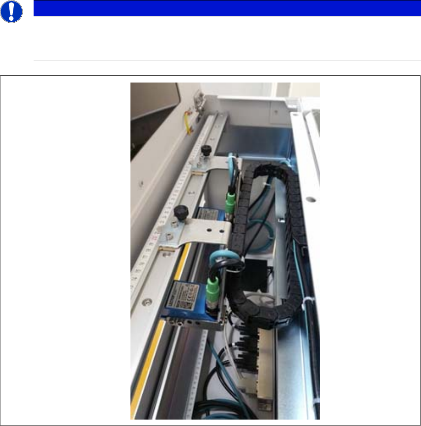
Fig. 7.4 - 12
Barcode readers - example
PLEASE NOTE
Barcode readers will be assembled according to customers order
The number of barcode readers is fitted according to the customer order. The maximum
number of barcode readers is 4 per assembly kit.
Assembly and Instruction Manual 7 Barcode reader extension
Shuttle Extension Edition 11/2018 7.4 Assembly Instruction
87
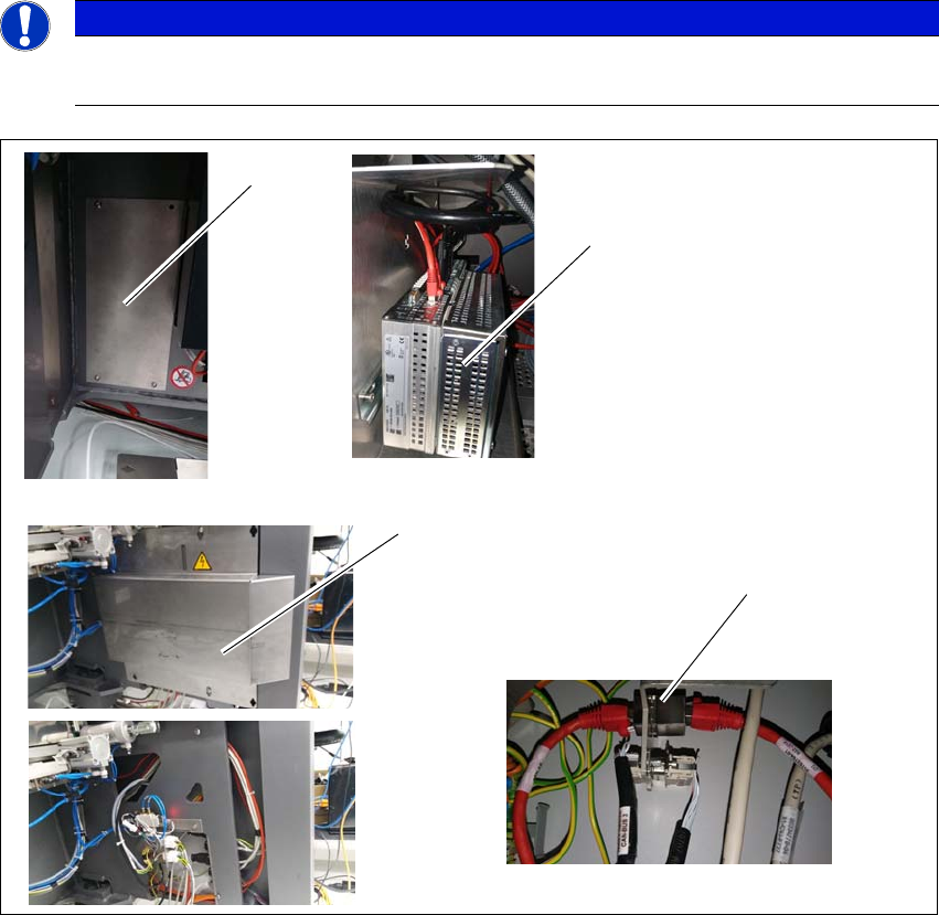
7.4.13 Step 13
Remove SIPLACE TX machine cover of Box PC (1)
Install PCIe LAN card 03118416- into the Box PC (2).
Remove SIPLACE TX machine cover of external connections (3).
Install RJ45 adapter 03098416- into SIPLACE TX external connections (4).
Route the LAN cable 03148161- from the Box PC to the RJ45 adapter.
7
7
Fig. 7.4 - 13 Step 13
PLEASE NOTE
Powered down for this installation
SIPLACE TX machine must be powered down for this installation.
(1)
(2)
(3)
(4)

7 Barcode reader extension Assembly and Instruction Manual
7.4 Assembly Instruction Shuttle Extension Edition 11/2018
88
7.4.14 Barcode readers - overview
The standard scan distance for the barcode reader is 80 mm from the PCB surface. Nonetheless,
both top and bottom barcode reader assembly can be adjusted to 60mm to allow reading smaller
code cells.
7
Fig. 7.4 - 14 Barcode readers - overview
Assembly kit PCB barcode
top
Assembly kit PCB bar
-
code bottom
PCB
Rail extension + belt+ pulleys