SL940-Install-Ops-Maintenance-7210918_B.pdf - 第114页
6-6 Configurati on and C hara cterizat ion 6.6 Bea con Configur ati on The be ha vior of the Light Beacon can b e customiz ed to respond to the I /O states of custom er equipm ent added to the system . Beacon C onfigurat…
Configuration and Characterization 6-5
6.5 Camera Configuration
NOTE ECXP is configured at the factory for your particular coating system. If you should need
to reconfigure the camera, follow the steps below.
To configure the Genie Camera:
1. Select
Configure > Reconfigure from the ECXP Edit Screen.
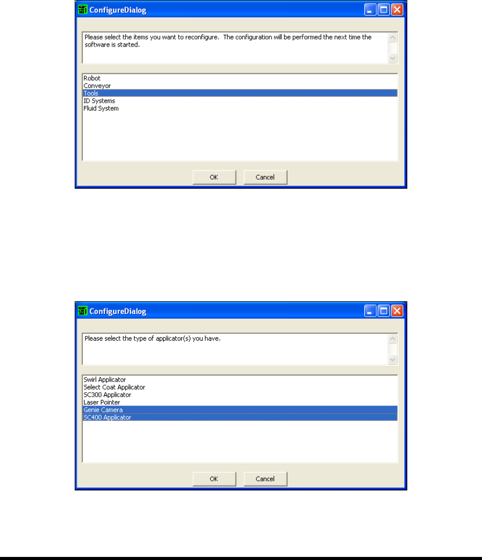
2. When prompted to select the item to be reconfigured (Figure 6-4), select
Tools and click OK.
Figure 6-4 Reconfiguring ECXP Tools
3. Restart the ECXP software. When prompted to select an applicator:
a. Select
Genie Camera.
b. Press the <
Ctrl> key and select the appropriate coating applicator (Figure 6-5) and then
click
OK.
Figure 6-5 Configuring ECXP for the Genie Camera
4. After you have responded to all the on-screen prompts, the ECXP program will start.
6-6 Configuration and Characterization
6.6 Beacon Configuration
The behavior of the Light Beacon can be customized to respond to the I/O states of customer equipment
added to the system. Beacon Configuration is only turned on if both Custom System and Configurable
Beacon option are chosen during initial system configuration or reconfiguration. A separate beacon.ini
file is used to store the beacon configuration settings. The operation of the beacon depends on the
machine firmware. Some versions of the firmware may have priority over the beacon function.
NOTE ECW only monitors inputs and outputs when it is not busy running a product program or
procedure. If an input or output should change state during production, the beacon will
not be turned on until the current program or procedure is completed.
To set Beacon Configuration:
1. Configure the system as Custom. See 6.4.2 ECXP Reconfiguration.
Alternatively, you may edit the ECW.ini file. Find the [Workcell1] section and set
Has Configurable Beacon=1.
2. Decide what components you want to monitor.
You must know the I/O number for each of the components.
3. Create a Log Trigger Fault.
a. Click on
Configure > Status Monitoring > Log Trigger Fault.
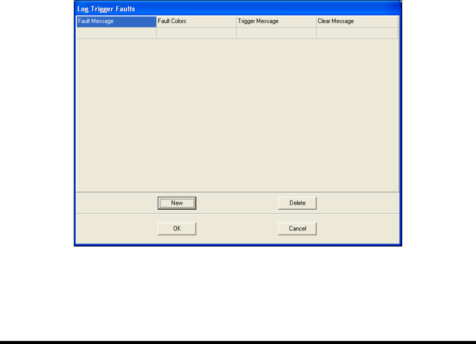
b. Click on
New to add a new Trigger Fault (Figure 6-6).
Figure 6-6 Log Trigger Faults Dialog Box
c. Click on the Fault Message field and type in a short fault message.
This message will be displayed on the Fault Monitor.
Configuration and Characterization 6-7
d. Click on the Fault Color field and select a color.
This is the color of the Fault Message displayed on the Fault Monitor.
e. Click on the
Trigger Message field and select a trigger for the fault from the dropdown
menu, or type in any other message that goes into the fault log.
f. Click on the
Clear Message field and select the event that clears the message from the
dropdown menu, or type in any other message that goes into the fault log.
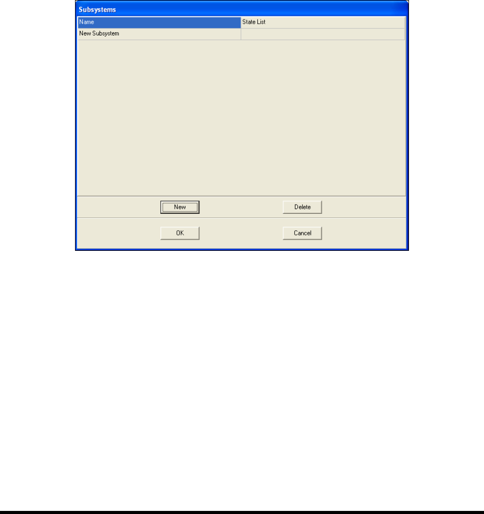
4. Create a Subsystem.
a. Click on
Configure > Status Monitoring > Beacon Configuration > Subsystems.
b. Click on
New.
Figure 6-7 Subsystem Dialog Box
c. Click on the Name field and type in a name for the subsystem.
d. Click on the
State List field, then the More button in the field.
The State List dialog opens.
e. Click on
New twice to create two states.
f. Click in the
Name field and give each state a name, such as On or Off, or Open or Closed.
g. Click in the
Trigger fields and select an input from the dropdown menu or type in a log
message.