SL940-Install-Ops-Maintenance-7210918_B.pdf - 第58页
3-8 Inst allat ion 3.6 Installi ng the Light Beacon 1. Loosen the five (5) s crews on the elect ronics /pneum atics cover and rem ove it. 2. Remove the fe rrite be ad fro m the cable . 3. Feed the elec trical cable on th…
Installation 3-7
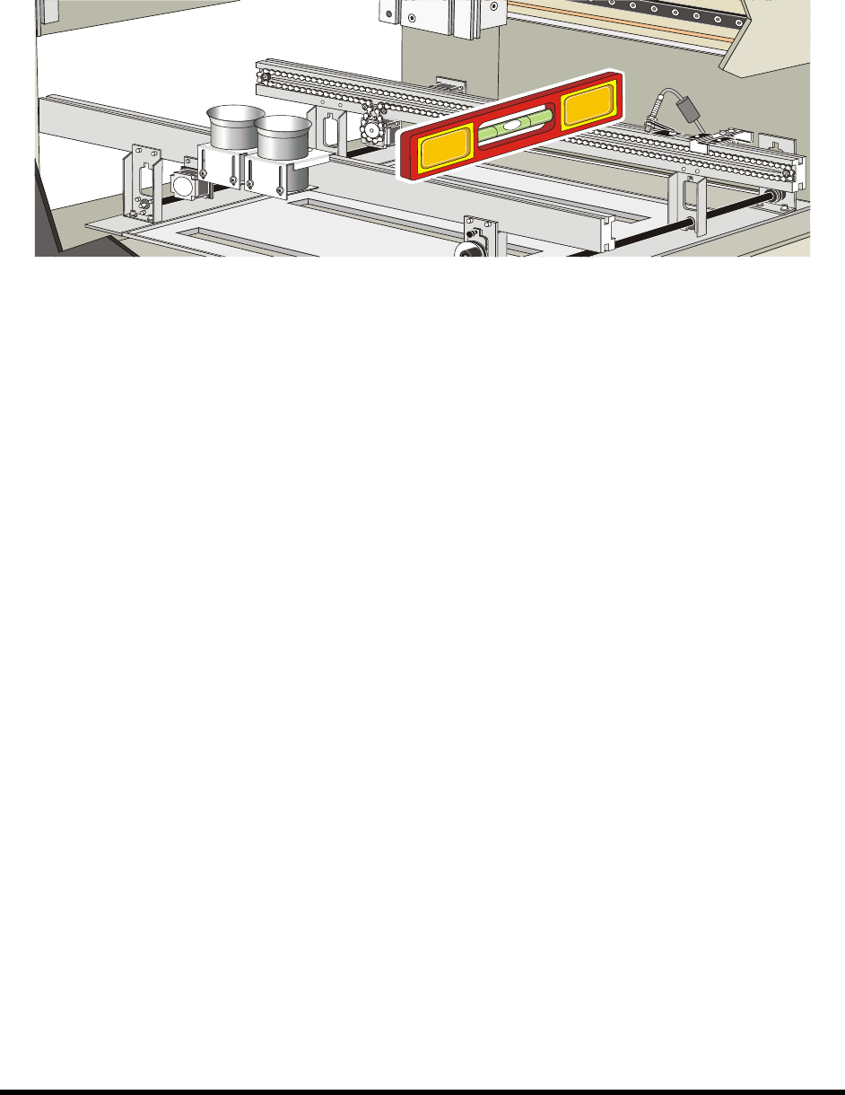
4. Place the box level between the front and rear conveyor rails along the Y-axis (Figure 3-7).
5. Observe the position of the bubble within the level’s window.
The bubble should be centered, indicating coating system is level from front-to-back.
Figure 3-7 Leveling the Coating System – Y-Axis
6. If necessary, adjust the levelers (Figure 3-6) of the coating system as follows:
a. If necessary, loosen the 1 1/2-inch lock nut on the leveler.
b. Turn the 1 1/2-inch post nut in the desired direction until the level’s bubble is centered,
indicating that the system is level from front-to-back.
Turning the post nut clockwise raises the coating system. Turning the post nut
counterclockwise lowers the coating system.
7. Check the system for stability by pressing up and down on one of the top corners of the
coating system. If one leveler is lower or higher than the others, the coating system will rock
back and forth. Adjust the levelers so that they are all bearing the weight equally.
8. Re-level the coating system from side-to-side and from front-to-back, if necessary.
3-8 Installation
3.6 Installing the Light Beacon
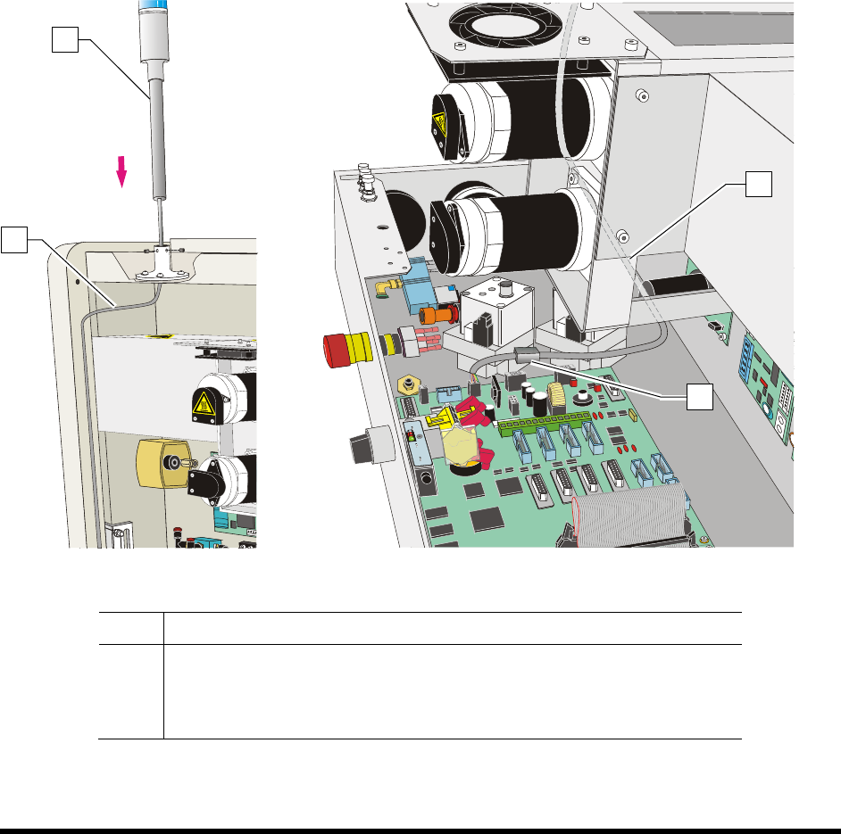
1. Loosen the five (5) screws on the electronics/pneumatics cover and remove it.
2. Remove the ferrite bead from the cable.
3. Feed the electrical cable on the light beacon through the top of the light beacon base
(Figure 3-8A).
4. Set the light beacon into the base and tighten the set screws.
5. Route the electrical cable as shown in Figure 3-8A and Figure 3-8B.
6. Make the beacon electrical connections (Figure 3-8B).
7. Replace the ferrite bead.
8. Replace the electronics/pneumatics cover and tighten the screws that hold the panels in place.
Figure 3-8A
Figure 3-8B
Item Description
1 Beacon
2 Electrical Cable
3 Ferrite Bead
Figure 3-8 Installing the Light Beacon
1
2
2
3
Installation 3-9
3.7 Installing the Laptop Computer
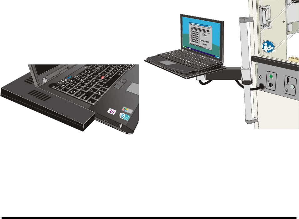
NOTE The laptop computer is shipped from the factory fully charged
1. Remove the laptop computer from its packaging.
2. Remove the keys from the lock and give them to the person responsible for the machine.
The keys are used to lock the laptop computer to the dispensing system tray.
3. Move the laptop tray arm bracket on the dispensing system so that the laptop tray is facing
forward.
4. Attach the USB and Network cables and grounding wire attachment to their respective ports
on the computer.
5. Attach the power cable to the rear of the computer.
NOTE The laptop is adhered to the tray with a hook and loop fastener. Align the laptop
computer before placing it on the tray.
6. With the laptop lid closed, align the computer with the covers such that no gaps exist on the
left hand side or the back edge.
7. Gently press the laptop onto the base.
8. Attach the locking cable to the laptop.
Figure 3-9 Aligning the Computer to the Tray Figure 3-10 Laptop Computer Installed