SL940-Install-Ops-Maintenance-7210918_B.pdf - 第124页
6- 16 Configuration a nd C haracte rization 6.12 Robot Configur ati on 6.12.1 H ome The Home position o f the Robot is a k nown position within its work space defined by X, Y, and Z coordinate limit sw itches. When the R…
Configuration and Characterization 6-15
6.11 Inverter Configuration
NOTE You may configure the Inverter through the Conveyor Configuration dialog box or
through the Reconfigure feature. The recommended method is through the Conveyor
Configuration dialog box. If you use the Reconfigure feature, all conveyor settings are
reset to the factory defaults. You will then have to restore any customized settings. The
following procedure uses the Conveyor Configuration dialog box. The Reconfigure
method is detailed in 6.4.2 ECXP Reconfiguration.
To configure the Inverter:
1. Click on
Configure > Conveyor Settings from the ECXP Edit Screen menu bar.
The Conveyor Settings dialog box shown in Figure 6-13 opens.
2. Enter the desired values.
See Table 6-2 for a description and default value for each property.
3. Click
OK when done.
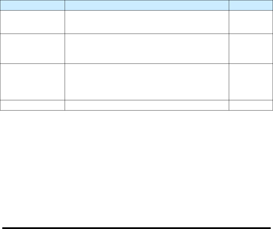
Table 6-2 Inverter Configuration
Property Description Default Value
Invert Move 1
Distance to move the board into the Inverter. This move is
used when the Inverter is upstream of workcell. If the Inverter
is upstream, must be a negative value.
-1000 mm
Invert Move 2
Distance to move the board upstream after it passes the
fixture sensor. This move is only used when the Inverter is
downstream of the workcell. This move is a safety factor to
prevent damage to the board. Must be a negative value.
-30 mm
Inverter Time Out
Time to wait for the board to be sent to the Inverter and return.
The timeout counter starts when the conveyor sends the
board to the Inverter. If the inverted board fails to load into the
fixture before the timeout interval expires, production stops
and the "Board Failed To Load" error message appears.
15 sec.
Inverter Type Upstream or Downstream configurations are supported. Upstream
6-16 Configuration and Characterization
6.12 Robot Configuration
6.12.1 Home
The Home position of the Robot is a known position within its workspace defined by X, Y, and Z
coordinate limit switches. When the Robot is at the Home position, the coordinates of the tool flange in
the Base Frame are X=0, Y=0, Z=3.5 inches. The Z-axis is all the way up in the Home position, and all
the way down when at the origin position. See 6.12.2 Reference Frames for additional information.
If the Robot loses track of its current position, it performs a homing operation, which is a sequence of
slow motions to the Home position, where the limit switches sense the Robot's arrival. The Robot then
resets its position to the Home position. To ensure coating accuracy, you can add a Position Verify
instruction to a product program or procedure.
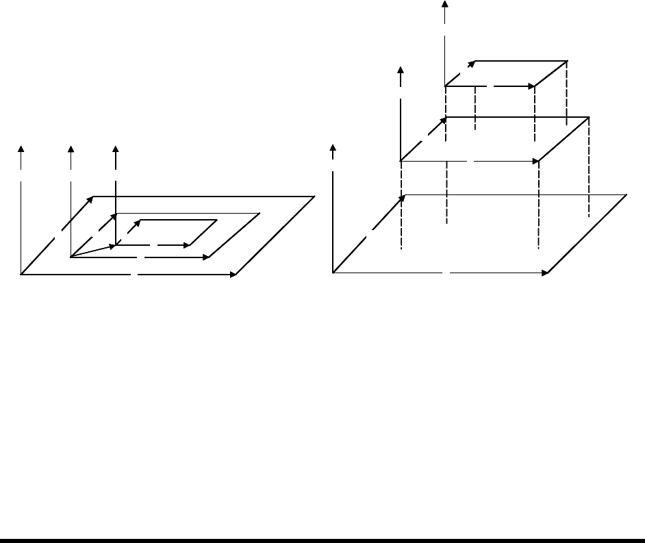
6.12.2 Reference Frames
All positioning in the workcell is done with reference to sets of position coordinates, called Reference
Frames. In ECXP, three different sets of Reference Frames are used: Base Frame, Product Frame, and
Pattern Frame. See Figure 6-14. As you face the front of the workcell, the X-axis is left to right, the Y-
axis is front to rear, and the Z-axis is up and down. The X, Y, and Z limit switches at the front left corner
of the Base Frame define the Home or Origin position of the Robot. The Z-axis is all the way up in the
Robot Home position.
A
X
Y
Z
B
X
Y
Z
C
X
Y
Z
0,0,0
A
X
Y
Z
C
X
Y
Z
B
X
Y
Z
A
X
Y
Z
B
X
Y
Z
C
X
Y
Z
0,0,0
A
X
Y
ZZ
B
X
Y
ZZ
C
X
Y
Z
0,0,0
A
X
Y
Z
C
X
Y
Z
B
X
Y
Z
A
X
Y
Z
A
X
Y
Z
C
X
Y
Z
C
X
Y
Z
C
X
Y
Z
C
X
Y
Z
B
X
Y
Z
B
X
Y
Z
Figure 6-14 Reference Frames
6.12.2.1 Base Frame
The Base Frame (See Figure 6-14, Rectangle A) is the set of coordinates (X, Y, and Z) that define the
Robot's travel. The origin (Home) of the Base Frame is a known point in the workspace, defined by a set
of limit switches. In the Base Frame, the Z-axis is all the way down. When you configure the fixture, you
teach the Z offset from the Base Frame Z by teaching Z with the nozzle touching the substrate. See 6.9
Fixture Configuration. Items that reference the Base Frame are:
• All procedures (maintenance subroutines)
• Fixture Constraint Location
• Safe Z Height
Base Frame
Product Frame
Frame
Pattern
Actual View
Exploded View
Configuration and Characterization 6-17
6.12.2.2 Product Frame
Product Frames (See Figure 6-14, Rectangle B) exist within the Base Frame. ECXP uses fixture
constraint coordinates, plus the length and width of the product, to calculate the coordinates of the
Product Frame within the Base Frame. The Product Frame origin is the calculated Main Pattern Edit
Frame.
NOTE A product can be a board or a pallet (carrier) containing one or more boards. If a pallet
is used, the dimensions of the pallet are used to calculate the Product Frame.
6.12.2.3 Pattern Frame
The origin coordinates of patterns (See Figure 6-14, Rectangle C) other than the Main Pattern are
expressed as a set of coordinates in the Product Frame. The pattern origin coordinates are stored in the
Pattern Edit Frame when the pattern is created.
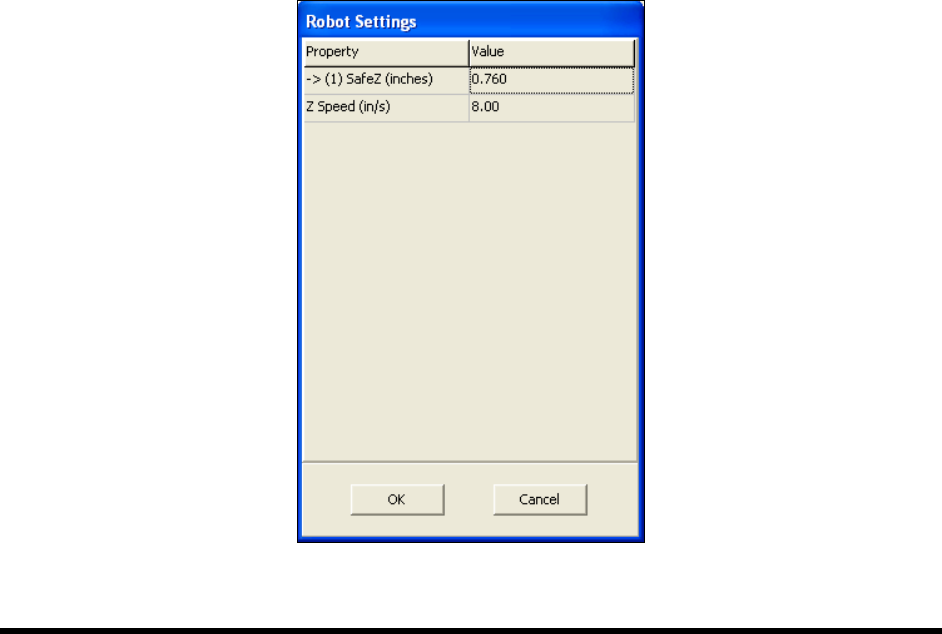
6.12.3 Robot Settings
The Robot Settings dialog box in ECXP is used to set the Safe Z Height and Z-Speed.
To set the Safe Z Height and Z-Speed:
NOTE The Z-Height should be set using the Base Reference Frame which represents the entire
robot travel area. See 6.12.2.1 Base Frame.
1. Click on
Configure > Robot Settings from the ECXP Edit Screen menu bar.
The Robot Settings dialog box opens. See Figure 6-15.
Figure 6-15 Robot Settings Dialog Box