SL940-Install-Ops-Maintenance-7210918_B.pdf - 第55页
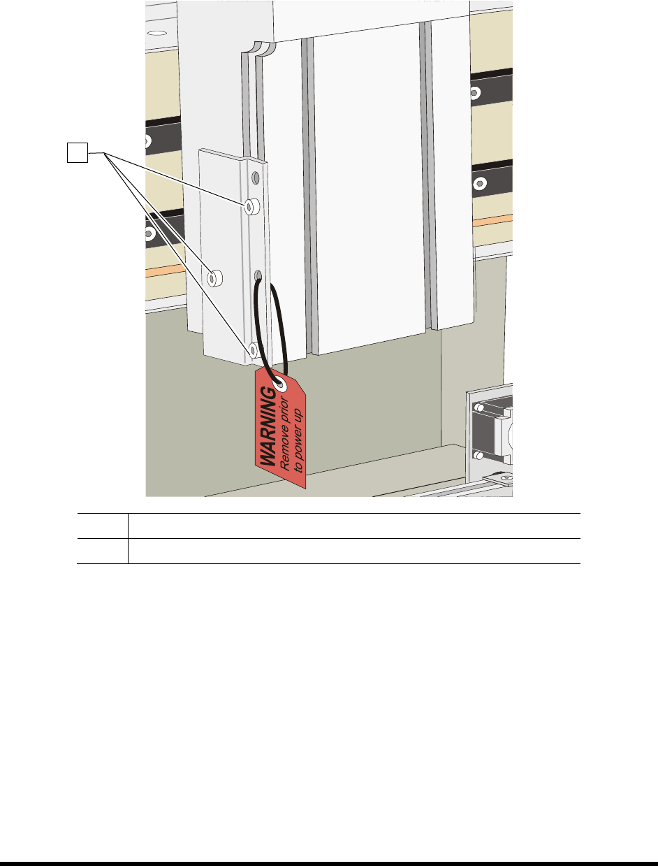
Insta llat ion 3-5 4. Rem ove the sh ipp ing brack et and warn ing tag attac hed to t he Z - Head by loosenin g the screws. See Figur e 3-4. Retain bracket and ha rdware for fu ture shipp ing purposes. Item Descripti o…
3-4 Installation
3.4 Unpacking the Coating Area
To unpack the Coating Area:
1. Remove all tie wraps, tape, foam packing material, and warning tags from the following
areas:
• Dispensing Head (Robot)
• Conveyor
NOTE Location of packaging materials to be removed is indicated by the presence of
red warning tags. The amount, type, and arrangement of packaging materials will
depend on your system’s configuration.
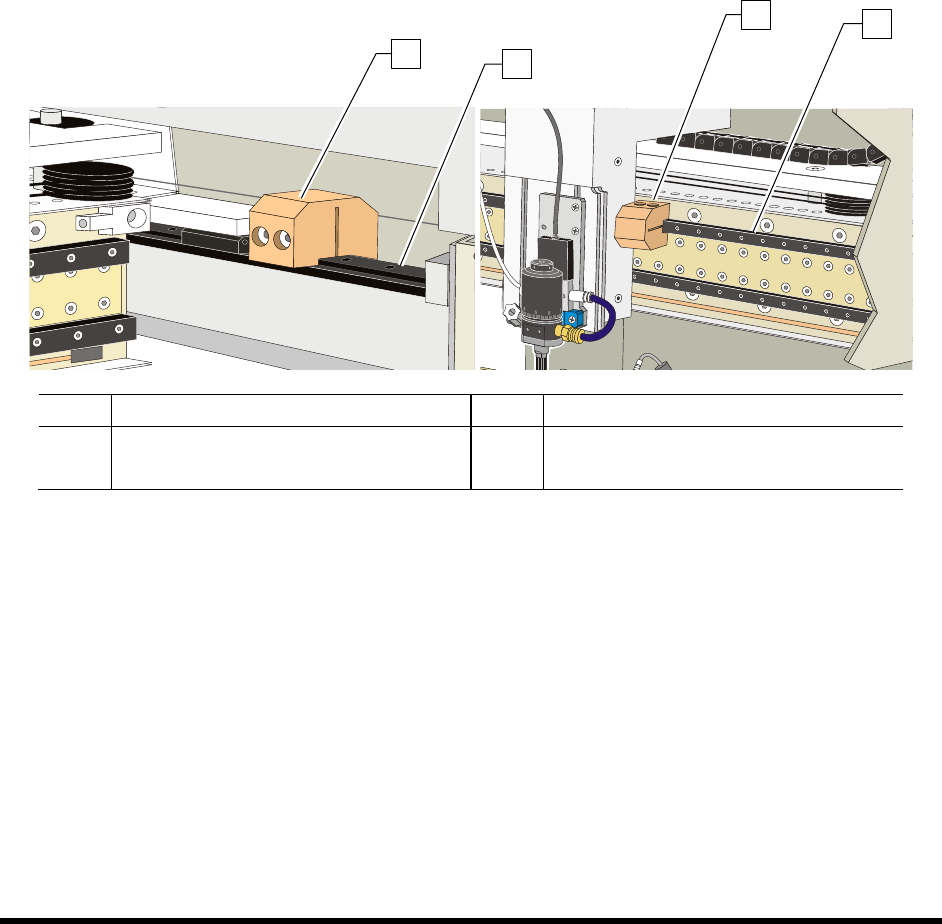
2. Loosen the 3 mm setscrews on the X- and Y-axis Dispensing Head Stoppers. See Figure 3-3.
3. Remove the stoppers and retain them in a safe place.
Item Description Item Description
1 Y-Axis Stopper 3 X-Axis Stopper
2 Y-Rail (right side) 4 X-Beam
Figure 3-3 Dispensing Head Stopper Locations
1
2
3
4
3-6 Installation
3.5 Leveling the Coating System
WARNING! CAUTION!
This procedure should only be performed by a trained service technician. The
system should be shutdown for service before performing this procedure. Refer
to 5.11.2.4 Service Shutdown.
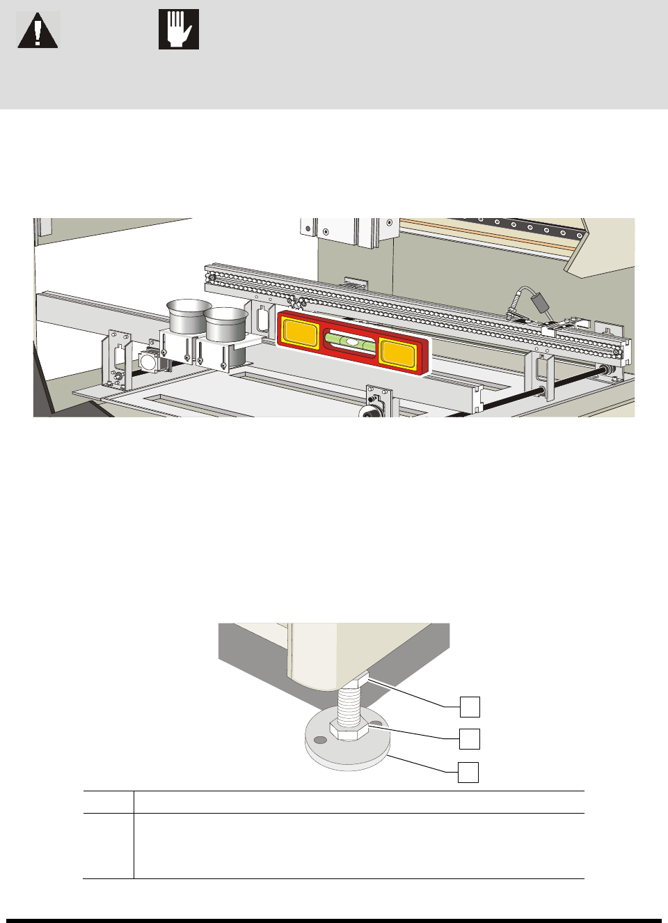
1. Place a box level on the conveyor rail along the X-axis (Figure 3-5).
2. Observe the position of the bubble within the level’s window.
The bubble should be centered, indicating the coating system is level from side-to-side.
Figure 3-5 Leveling the Coating System – X-Axis
3. If necessary, adjust the levelers (Figure 3-6) of the coating system as follows:
a. Loosen the 1 1/2-inch lock nut on the leveler if necessary.
b. Turn the 1 1/2-inch post nut in the desired direction until the level’s bubble is centered,
indicating that the system is level from side-to-side.
Turning the post nut clockwise raises the coating system. Turning the post nut
counterclockwise lowers the coating system.
Item Description
1 Lock Nut
2 Post Nut
3 Leveler
Figure 3-6 Coating System Levelers (Feet)
1
2
3