SL940-Install-Ops-Maintenance-7210918_B.pdf - 第155页
Parts Replacement 9-7 10. Bring the two ends of the c hain o ne chain - link length apart ( Figur e 9-8 ). 11. Insert m aster li nk’s male link into both ends of the ch ain so tha t pins are pointing outboard ( Fi gur e …
9-6 Parts Replacement
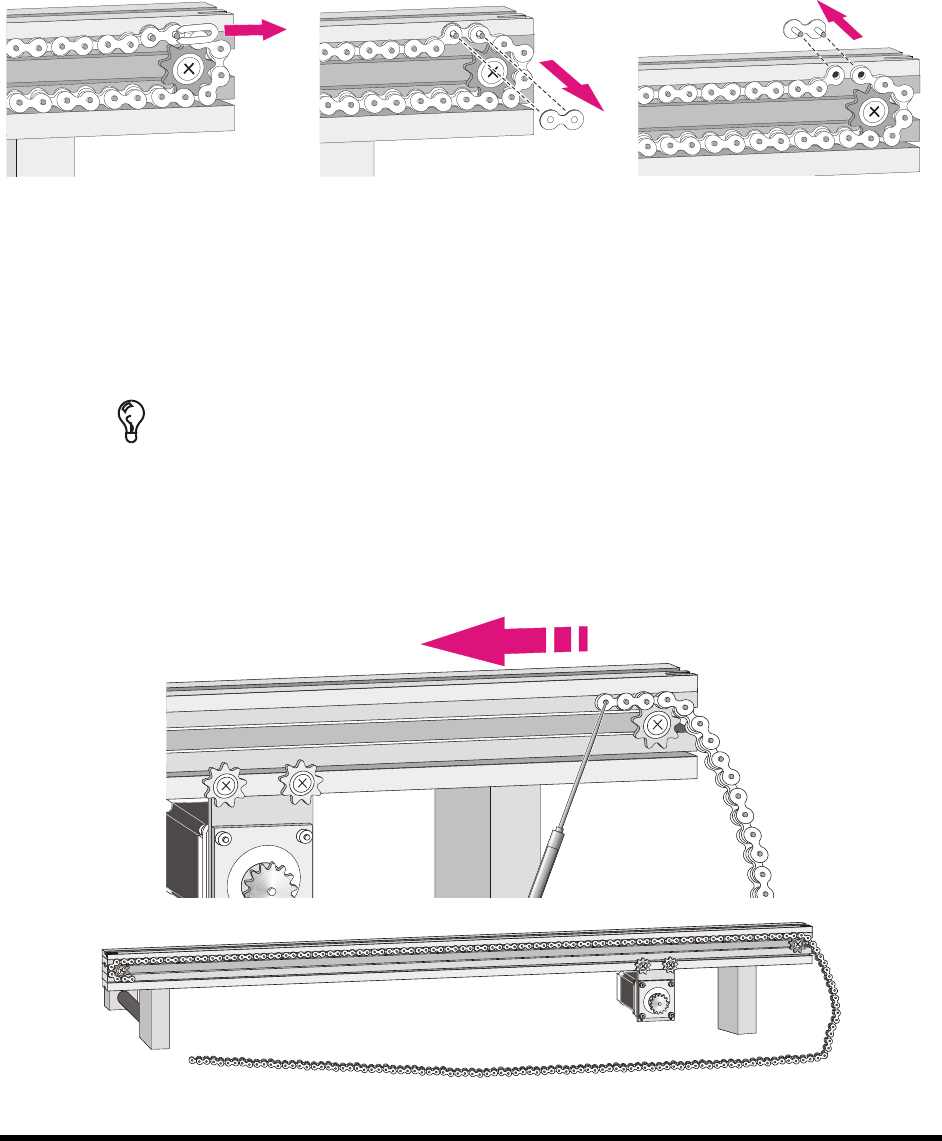
5. Locate the master link and use the pliers to remove it as described below:
a. Remove the retainer clip (Figure 9-4).
b. Remove the female link (Figure 9-5).
c. Remove the master link (Figure 9-6).
Figure 9-4 Removing the
Retainer Clip
Figure 9-5 Removing the
Female Link
Figure 9-6 Removing the Master
Link (Male Link)
6. Remove any rail-mounted components that interfere with chain removal/replacement.
7. Remove the old chain by sliding it off the conveyor sprockets.
TIP It is recommended that you remove and replace one chain at a time to ensure that
all parts removed from each rail are re-installed in their exact same locations.
8. Use isopropyl alcohol and clean swabs to clean all metal surfaces that make contact with the
chain, including sprockets and rails.
9. Install the new chain onto the sprocket rail (Figure 9-7).
Figure 9-7 Installing the Chain on the Sprocket Rail
Parts Replacement 9-7
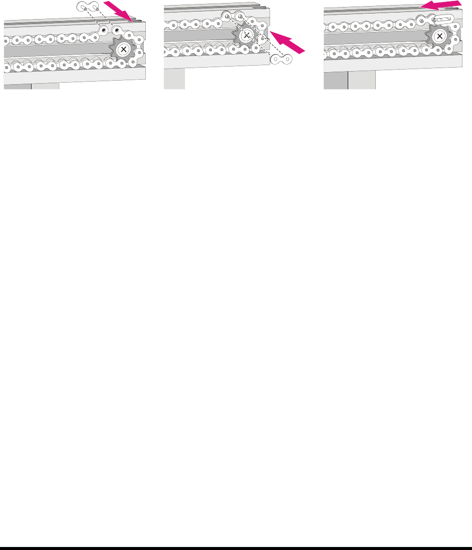
10. Bring the two ends of the chain one chain-link length apart (Figure 9-8).
11. Insert master link’s male link into both ends of the chain so that pins are pointing outboard
(Figure 9-8).
12. Attach the master link’s female link to both male link’s pins (Figure 9-9).
13. Slide the retainer clip onto male link’s pins. Ensure that the clip’s open end points in the
direction of the motor subassembly (Figure 9-10).
Figure 9-8 Inserting the Male
Link
Figure 9-9 Attaching the
Female Link
Figure 9-10 Installing the
Retainer Clip
14. Tension the chain by loosening the motor mounting screws allowing the motor’s weight to
remove the slack.
NOTE Slack should be eliminated with the motor’s weight (do not push the motor
down to create tension on the chain).
15. Perform a visual inspection of chain to ensure that slack from chain is eliminated.
16. Lock motor into position by tightening screws.
17. Perform a function check by revolving the chain 2 to 3 times through its complete range
of motion.
18. Replace any rail-mounted equipment that you removed in Step 6.
19. Repeat Steps 7-18 for the remaining chain.
20. Replace any coating system panels you may have removed.
9-8 Parts Replacement
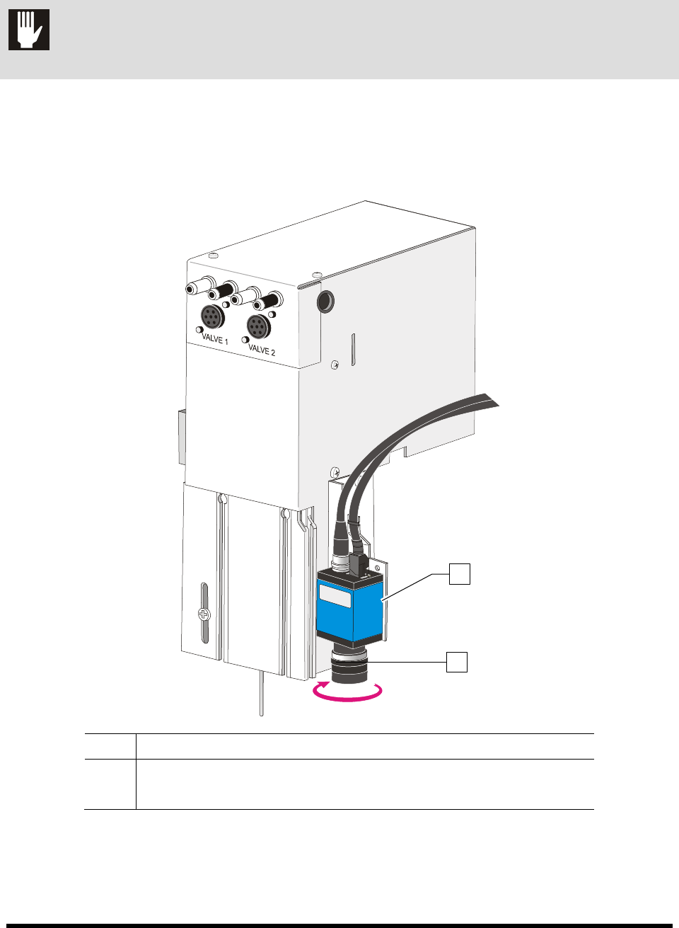
9.9 Replacing the Camera Lens
CAUTION! Except for lens replacement and lighting adjustments, all other configuration and
adjustments should only be performed by a trained service technician.
To remove and replace the camera lens:
1. Remove the lens by turning the lens tube counterclockwise (Figure 9-11).
2. Screw on the replacement lens by turning the lens tube clockwise.
Item Description
1 Camera
2 Lens Tube
Figure 9-11 Replacing the Camera Lens
2
1