SL940-Install-Ops-Maintenance-7210918_B.pdf - 第115页
Configuration a nd C haract erization 6- 7 d. Click on t he Fault Color field and select a co lor. This is the c olor of the Fau lt Me ssage d isplay ed on the Fault Mon itor. e. Click on the Trigg er Messag e field an…
6-6 Configuration and Characterization
6.6 Beacon Configuration
The behavior of the Light Beacon can be customized to respond to the I/O states of customer equipment
added to the system. Beacon Configuration is only turned on if both Custom System and Configurable
Beacon option are chosen during initial system configuration or reconfiguration. A separate beacon.ini
file is used to store the beacon configuration settings. The operation of the beacon depends on the
machine firmware. Some versions of the firmware may have priority over the beacon function.
NOTE ECW only monitors inputs and outputs when it is not busy running a product program or
procedure. If an input or output should change state during production, the beacon will
not be turned on until the current program or procedure is completed.
To set Beacon Configuration:
1. Configure the system as Custom. See 6.4.2 ECXP Reconfiguration.
Alternatively, you may edit the ECW.ini file. Find the [Workcell1] section and set
Has Configurable Beacon=1.
2. Decide what components you want to monitor.
You must know the I/O number for each of the components.
3. Create a Log Trigger Fault.
a. Click on
Configure > Status Monitoring > Log Trigger Fault.
b. Click on
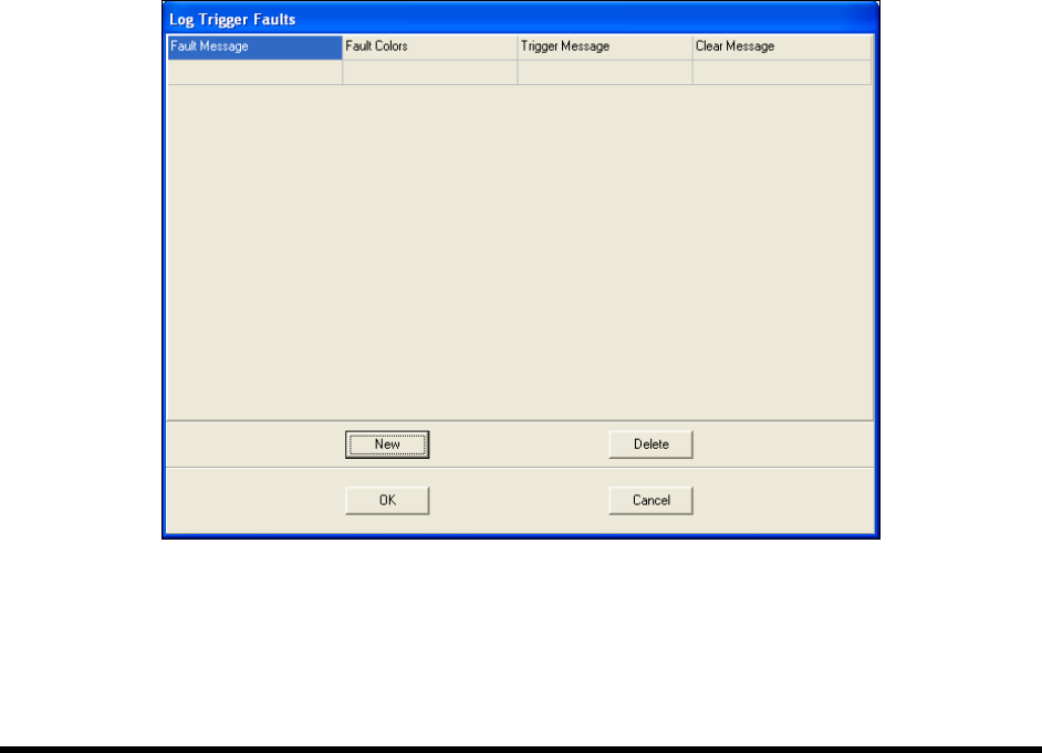
New to add a new Trigger Fault (Figure 6-6).
Figure 6-6 Log Trigger Faults Dialog Box
c. Click on the Fault Message field and type in a short fault message.
This message will be displayed on the Fault Monitor.
Configuration and Characterization 6-7
d. Click on the Fault Color field and select a color.
This is the color of the Fault Message displayed on the Fault Monitor.
e. Click on the
Trigger Message field and select a trigger for the fault from the dropdown
menu, or type in any other message that goes into the fault log.
f. Click on the
Clear Message field and select the event that clears the message from the
dropdown menu, or type in any other message that goes into the fault log.
4. Create a Subsystem.
a. Click on
Configure > Status Monitoring > Beacon Configuration > Subsystems.
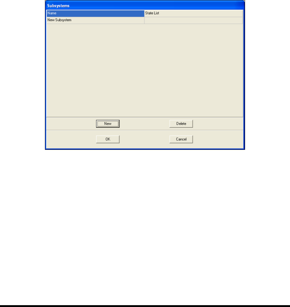
b. Click on
New.
Figure 6-7 Subsystem Dialog Box
c. Click on the Name field and type in a name for the subsystem.
d. Click on the
State List field, then the More button in the field.
The State List dialog opens.
e. Click on
New twice to create two states.
f. Click in the
Name field and give each state a name, such as On or Off, or Open or Closed.
g. Click in the
Trigger fields and select an input from the dropdown menu or type in a log
message.
6-8 Configuration and Characterization
6.7 Tool Configuration
A tool consists of a coating applicator and nozzle. The Tool Configuration dialog box allows you to set
the offset for each tool and perform a characterization.
6.7.1 Tool Offset
Tool Offset is the X, Y, and Z distance from the lower tooling pin on the Z slide (also called the tool
flange, or tool arm) to the tool tip (end of nozzle). The offset for each tool must be entered into ECXP so
that the robot can position the tool tip accurately when running product programs.
To define Tool Offsets:
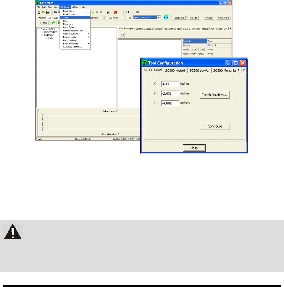
1. Click on
Configure > Tools from the Edit Screen menu bar (Figure 6-8).
The Tool Configuration dialog box opens.
Figure 6-8 Tool Configuration Dialog Box
2. Select the desired tool tab.
3. Enter the appropriate tool offsets for the X, Y, and Z fields.
Since the tool tip is in front of and below the tooling pin, the Y and Z offsets are always
negative. Positive X is to the right of the tooling pin.
WARNING! If Tool Offsets have already been defined and set up in the Tool Library,
correct offsets are displayed in the Tool Configuration dialog box. DO NOT
change them without assistance from your Asymtek representative. Your
Asymtek application engineer can supply you with the offset coordinates for
each tool used.