SL940-Install-Ops-Maintenance-7210918_B.pdf - 第119页
Configuration a nd C haract erization 6- 11 To configure a fixture: NOTE Before configuring the fixture, you m ust configure the Tool Offs et s. Refer to 6.7 Tool Configuration fo r detailed instruction s. 1. To config…
6-10 Configuration and Characterization
6.9 Fixture Configuration
Fixture refers to the location inside the work area used as a consistent and repeatable point for positioning
and queuing the product to be coated. It consists of both position (XYZ) coordinates and a corner
constraint (Front Left, Front Right, Back Left, or Back Right). On conveyorized systems, the fixture is
typically the combination of a clamp and a stop. On non-conveyorized systems, it is usually a manual
fixture.
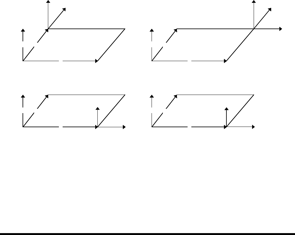
6.9.1 Fixture Constraint Location
ECXP uses the fixture constraint coordinates and the length and width of the board or carrier to determine
the Main Pattern Edit Frame coordinates. The fixture constraint location is the corner of the product that
is always in the same location when the product is in the fixture (the repeatable corner). ECXP calculates
the position of the front-left corner of the product from the repeatable corner, using the product's length
and width.
Conveyorized systems will always use a front corner as the constraint location, because the fixed rail is
located at the front of the workcell. For example, if the conveyor movement is from left to right, and the
fixed rail is the front rail, then the constraint location is
Front Right. If the conveyor movement is right to
left, then the constraint location is
Front Left.
X
Y
Z
X
Y
Z
X
Y
Z
X
Y
Z
Constraint is Front Left Constraint is Front Right
Constraint is Back Left Constraint is Back Right
2
1 1
2
1, 2
1
2
1. Main Pattern Edit Frame
2. Repeatable Corner
X
Y
Z
X
Y
Z
X
Y
Z
X
Y
Z
X
Y
Z
X
Y
Z
X
Y
Z
X
Y
Z
X
Y
Z
X
Y
Z
X
Y
Z
X
Y
Z
Constraint is Front Left Constraint is Front Right
Constraint is Back Left Constraint is Back Right
2
1 1
2
1, 2
1
2
1. Main Pattern Edit Frame
2. Repeatable Corner
Figure 6-10 Fixture Constraint Location
Configuration and Characterization 6-11
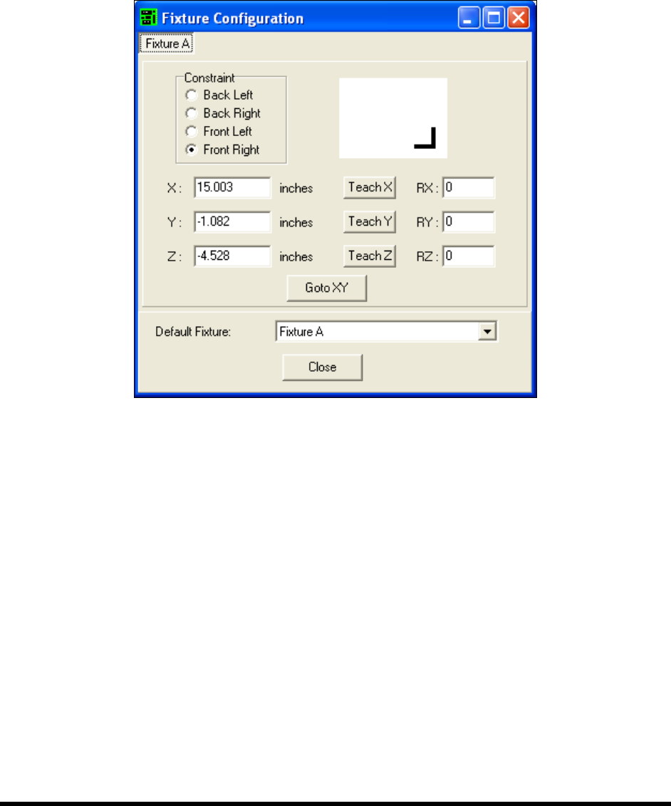
To configure a fixture:
NOTE Before configuring the fixture, you must configure the Tool Offsets. Refer to 6.7 Tool
Configuration for detailed instructions.
1. To configure a fixture, click on
Configure > Fixtures from the ECXP Edit Screen.
The Fixture Configuration dialog box shown in Figure 6-11 opens.
Figure 6-11 ECXP Fixture Configuration
2. Click on the tab for the fixture you are configuring.
There will be a separate tab for each fixture configured in ECXP.
3. Teach each coordinate separately as described below. See Figure 6-12 for coordinate
locations.
NOTE The coating applicator must be installed on the robot to teach the X and Y-
coordinates.
a. To teach the X-coordinate, move the coating applicator until the point is directly over
the leading edge of the board (X-coordinate on the Top View) and click on the
Teach X button.
b. To teach the Y-coordinate, move the coating applicator until the point is directly over
the front edge of the board (Y-coordinate on the Top View) and click on the
Teach Y
button.
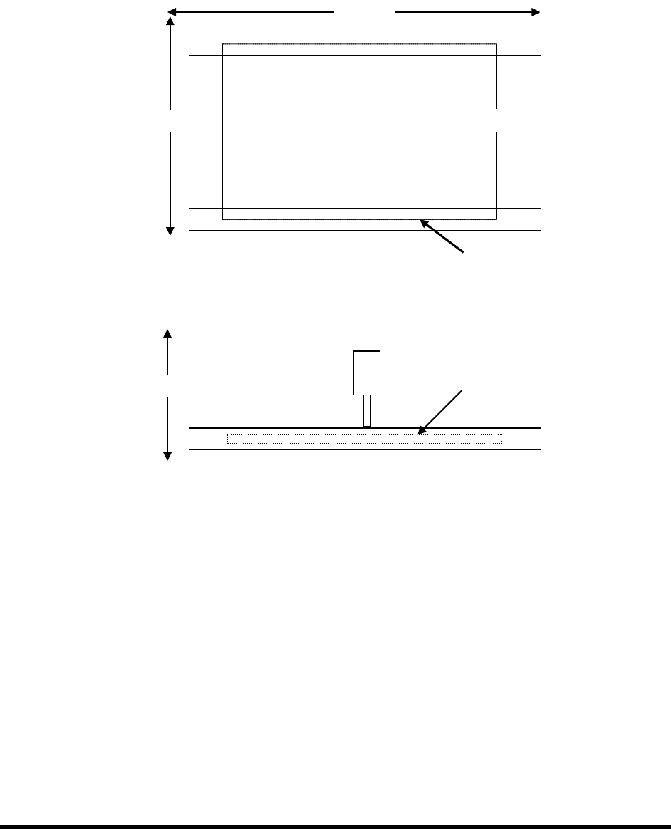
6-12 Configuration and Characterization
4. Install the nozzle used to configure the tool on the coating applicator to teach the
Z-coordinate. See Figure 6-12 for coordinate location.
a. To teach the Z-coordinate, carefully lower the nozzle until it is just touching the
surface of the board (Z-coordinate on the Side View) .
b. Click on the
Teach Z button.
Figure 6-12 Teaching XYZ Coordinates
X-Axis
Y-Axis
Z
Side View
Y
Top View
X
Z-Axis