SL940-Install-Ops-Maintenance-7210918_B.pdf - 第63页
Pow er - up an d Test in g 4-3 4.6 Connecting Pow er and Air Suppl y WARNING ! CAUTION! Make s ure that your fac ility m eets all requ irem ents liste d i n Sect ion 1 0 - Specificat ions . Failure to meet t hese req uir…

4-2 Power-up and Testing
4.4 Electrical Connections
The coating system requires 200/240 VAC 50/60Hz, 10A.
NOTE Refer to Section 10 - Specifications for more information on electrical requirements.
Contact your Asymtek representative for your particular system requirements.
Refer to Appendix B for SL-940E/SL-941E electrical diagrams and electronic connections.
4.5 Exhaust Connection
The coating system requires a 15.3 cm (6 inch) diameter exhaust duct capable of drawing a minimum of
17 m
3
/min @ 25.4 mm water column (600 SCFM air at 1.0 inch water column) static pressure.
NOTE Refer to Section 10 - Specifications for more information on exhaust requirements.
Contact your Asymtek representative for your particular system requirements.
Power-up and Testing 4-3
4.6 Connecting Power and Air Supply
WARNING! CAUTION!
Make sure that your facility meets all requirements listed in Section 10 -
Specifications. Failure to meet these requirements could result in serious bodily
injury to personnel and damage to the coating system.
CAUTION! This procedure should only be performed by a trained service technician.
Tools and Materials Needed:
• Main Power Cable
• Quick Release Air Hose Nozzle
To connect the facilities power and air supply:
CAUTION! Switch the Main Circuit Breaker to the OFF (0) position before proceeding.
1. Unpack the main power cable and remove all packing material including plastic wrappers and
tie wraps.
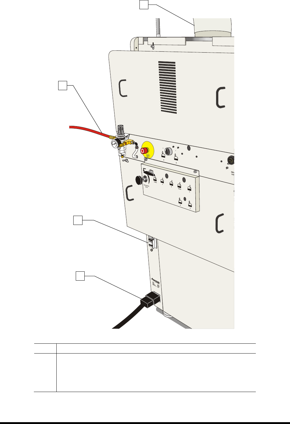
2. Plug the female end of the power cable into the main power inlet on the lower left side of
the coating system. Plug the male end of the power cable into the facility power source
(Figure 4-1).
3. Locate and attach the quick disconnect air nozzle to the facility air hose.
4. Connect the facility air hose to the main air inlet connector on the back right side of the
coating system.
5. Connect the facility exhaust ventilation system ductwork to the exhaust vent duct
(Figure 4-1).
6. Adjust airflow to a minimum of 600 scfm with the front door closed.
4-4 Power-up and Testing
Item Description
1 Exhaust Vent
2 Main Air Inlet
3 Main Power Circuit Breaker
4 Main Power Cord
Figure 4-1 Connecting the Facilities Power and Air Supply (10A Power Manager shown)
2
3
4
1