SL940-Install-Ops-Maintenance-7210918_B.pdf - 第117页
Configuration a nd C haract erization 6- 9 6.8 Fan Wi dth Confi gurat ion If your system is equipped with the opt ional Laser F an Width Con trol feature, y ou will need to per form a Fan Width Setup. Fan Width Control i…
6-8 Configuration and Characterization
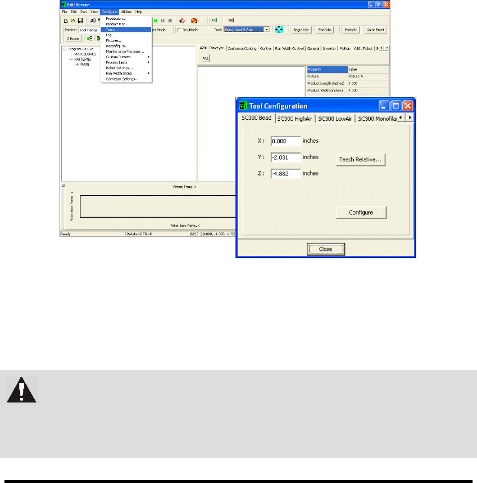
6.7 Tool Configuration
A tool consists of a coating applicator and nozzle. The Tool Configuration dialog box allows you to set
the offset for each tool and perform a characterization.
6.7.1 Tool Offset
Tool Offset is the X, Y, and Z distance from the lower tooling pin on the Z slide (also called the tool
flange, or tool arm) to the tool tip (end of nozzle). The offset for each tool must be entered into ECXP so
that the robot can position the tool tip accurately when running product programs.
To define Tool Offsets:
1. Click on
Configure > Tools from the Edit Screen menu bar (Figure 6-8).
The Tool Configuration dialog box opens.
Figure 6-8 Tool Configuration Dialog Box
2. Select the desired tool tab.
3. Enter the appropriate tool offsets for the X, Y, and Z fields.
Since the tool tip is in front of and below the tooling pin, the Y and Z offsets are always
negative. Positive X is to the right of the tooling pin.
WARNING! If Tool Offsets have already been defined and set up in the Tool Library,
correct offsets are displayed in the Tool Configuration dialog box. DO NOT
change them without assistance from your Asymtek representative. Your
Asymtek application engineer can supply you with the offset coordinates for
each tool used.
Configuration and Characterization 6-9
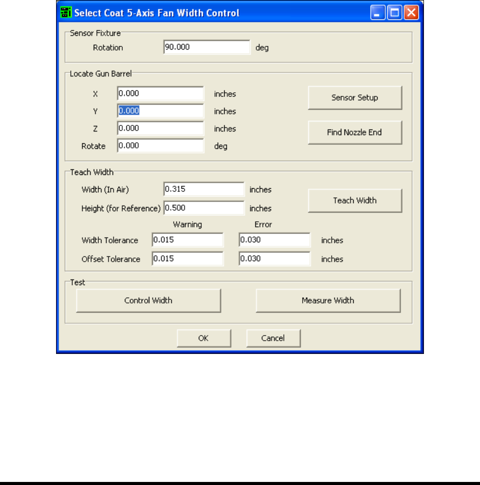
6.8 Fan Width Configuration
If your system is equipped with the optional Laser Fan Width Control feature, you will need to perform a
Fan Width Setup. Fan Width Control is available only for the Select Coat Tool. For more information,
contact your Asymtek representative.
To perform a fan width setup:
NOTE Before performing a fan with setup, you must perform a tool configuration and
characterization. Refer to 6.7 Tool Configuration and 6.14 Characterization for detailed
instructions.
1. Select
Configure > Fan Width Setup from the ECXP Edit Screen.
The Fan Width Control Dialog Box (Figure 6-9) opens.
Figure 6-9 ECXP Fan Width Setup Dialog Box
2. Enter the appropriate information and click OK. Refer to the ECXP User Guide, LFWC
Owner's Manual, or Online Help for assistance.
NOTE As part of the Fan Width Setup procedure, you will need to perform a FWC Sensor
Setup. For additional information, refer to the manual for your Laser Fan Width Control
System or contact your Asymtek representative.
6-10 Configuration and Characterization
6.9 Fixture Configuration
Fixture refers to the location inside the work area used as a consistent and repeatable point for positioning
and queuing the product to be coated. It consists of both position (XYZ) coordinates and a corner
constraint (Front Left, Front Right, Back Left, or Back Right). On conveyorized systems, the fixture is
typically the combination of a clamp and a stop. On non-conveyorized systems, it is usually a manual
fixture.
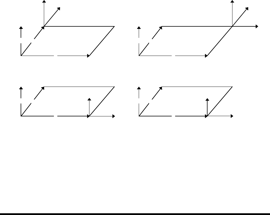
6.9.1 Fixture Constraint Location
ECXP uses the fixture constraint coordinates and the length and width of the board or carrier to determine
the Main Pattern Edit Frame coordinates. The fixture constraint location is the corner of the product that
is always in the same location when the product is in the fixture (the repeatable corner). ECXP calculates
the position of the front-left corner of the product from the repeatable corner, using the product's length
and width.
Conveyorized systems will always use a front corner as the constraint location, because the fixed rail is
located at the front of the workcell. For example, if the conveyor movement is from left to right, and the
fixed rail is the front rail, then the constraint location is
Front Right. If the conveyor movement is right to
left, then the constraint location is
Front Left.
X
Y
Z
X
Y
Z
X
Y
Z
X
Y
Z
Constraint is Front Left Constraint is Front Right
Constraint is Back Left Constraint is Back Right
2
1 1
2
1, 2
1
2
1. Main Pattern Edit Frame
2. Repeatable Corner
X
Y
Z
X
Y
Z
X
Y
Z
X
Y
Z
X
Y
Z
X
Y
Z
X
Y
Z
X
Y
Z
X
Y
Z
X
Y
Z
X
Y
Z
X
Y
Z
Constraint is Front Left Constraint is Front Right
Constraint is Back Left Constraint is Back Right
2
1 1
2
1, 2
1
2
1. Main Pattern Edit Frame
2. Repeatable Corner
Figure 6-10 Fixture Constraint Location