SL940-Install-Ops-Maintenance-7210918_B.pdf - 第24页
1- 10 Introduction 1.12 S y stem Features The fig ures in this secti on show view s and fea tures o f the coati ng sy stem . Callouts locate m ajor components, opt ions, and switches. The numbers asso ciated with the des…

Introduction 1-9
1.11.4 SC-300 Swirl Coat Applicator
The SC-300 Swirl Coat applicator offers three modes of operation - bead, monofilament and swirl. Ideal
for conformal coating applications, the SC-300 handles a wide range of materials, varying in viscosity
from 30 to 3500 mPa-sec (30 to 3500 centipoise). The SC-300 is designed for use with solvent-less
coatings, supporting environmentally responsible practices. A four-position tilt option is available to
allow coating access to vertical sides of components.
1.11.5 SC-400 PreciseCoat Conformal Coating Jet
The SC-400 PreciseCoat Conformal Coating Jet is ideal for applying conformal coating materials to
highly selective areas. This solution is designed for coating small substrates or substrates with high
component density, and when there are tight tolerances between coated and uncoated areas. The
SC-400 jet reaches locations not accessible by other applicators, using a needle design with jetting action
and fast pulse-width modulated control.
1-10 Introduction
1.12 System Features
The figures in this section show views and features of the coating system. Callouts locate major
components, options, and switches. The numbers associated with the descriptions correspond to the
callout numbers in the illustration. Detailed operating instructions for some of these features are treated in
other sections of this manual.
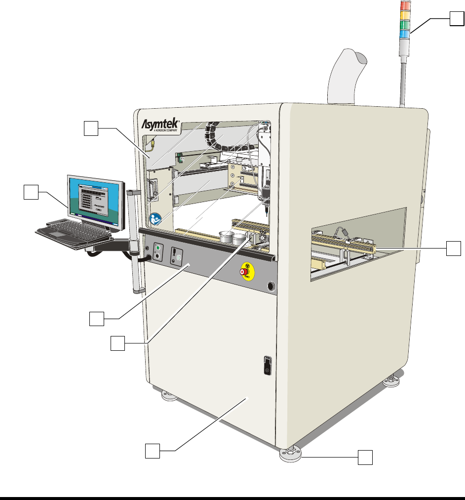
1.12.1 Front View Features
Below are functional descriptions of SL-940E/SL-941E components shown in Figure 1-3.
NOTE The terms Robot and Dispensing Head are synonymous and are used interchangeably
throughout this manual.
Figure 1-3A SL-940E Front View
8
1
2
3
6
4
5
7
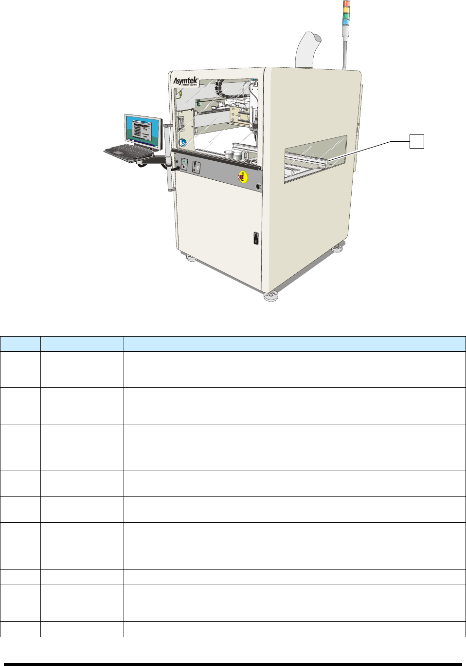
Introduction 1-11
Figure 1-3B SL-941E Front View (Tooling Rails shown)
Item Name Description
1 Front Hood
The Front Hood allows the operator to view and access the dispensing area. A
sensor connects the hood to the Safety Interlock System. If the hood is opened
when a program is running, all dispensing motion stops.
2 Laptop Computer
The coating system features a laptop computer, mounted on an adjustable
height bracket. The laptop computer runs the Easy Coat for Windows XP (ECXP)
coating software.
3 Front Panel
The Front Panel contains the system ON and OFF buttons, the Emergency
Machine Off (EMO) button, the Grounding Strap connection, and the Applicator
On/Off button. Refer to Section 5 - Operation for detailed descriptions of front
panel functions. See Figure 1-4.
4 Coating Area
The Robot, Solvent Cups, Conveyor, Stop Pins, and Board Sensors are all
located in the coating area. See Figure 1-5.
5 Front Cabinet
The Front Cabinet houses the Spill Pan, Laser Fan Width Control Amplifier
(optional), and the Reservoir Air Pressure Regulator. See Figure 1-7.
6
Levelers
(Foot Pads)
The Levelers are the footpads of the coating system. The levelers are adjusted
during installation and should not need attention unless the system is moved to a
new location. To protect the coating system from moving during an earthquake,
the levelers can be anchored to the floor. See 2.8 Earthquake Precautions.
7 Conveyor See 1.12.1.3 Conveyor.
8 Light Beacon
The Light Beacon signals the operator of system status by displaying a colored
solid or blinking light and/or issuing an audible tone. Refer to Section 2 - Safety
for additional information.
9 Tooling Rails See 1.12.1.2 Dispensing Area.
Figure 1-3 Front View
9