SL940-Install-Ops-Maintenance-7210918_B.pdf - 第157页
Parts Replacement 9-9 9.10 Replac ing Fuses If y our Sele ct Coa t SL - 940E/SL- 941E is equ ipped w ith a heated fluid system , there are tw o replaceab le fuses . See Tabl e 9- 1. CAUTIO N! Always replace fus es with f…
9-8 Parts Replacement
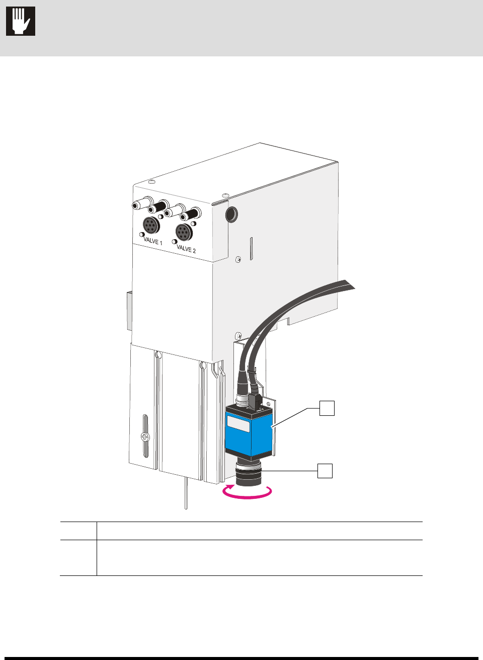
9.9 Replacing the Camera Lens
CAUTION! Except for lens replacement and lighting adjustments, all other configuration and
adjustments should only be performed by a trained service technician.
To remove and replace the camera lens:
1. Remove the lens by turning the lens tube counterclockwise (Figure 9-11).
2. Screw on the replacement lens by turning the lens tube clockwise.
Item Description
1 Camera
2 Lens Tube
Figure 9-11 Replacing the Camera Lens
2
1
Parts Replacement 9-9
9.10 Replacing Fuses
If your Select Coat SL-940E/SL-941E is equipped with a heated fluid system, there are two replaceable
fuses. See Table 9-1.
CAUTION! Always replace fuses with fuses of identical rating and size. Failure to do so may
not protect components from damage.
9.10.1 Replacement Fuses
Table 9-1 Replacement Fuses
Part Number Qty. Description Location
55-5391 1 FUSE, 4A, 5X20MM, TIME LAG Fluid System Heater
Tools and Materials Needed
•
ESD Grounding Strap
•
Replacement Fuse (see Table 9-1)
• Small Flat Head Screwdriver* • Phillips Screwdriver*
WARNING! CAUTION!
Fuse replacement should be performed by a trained service technician only.
9-10 Parts Replacement
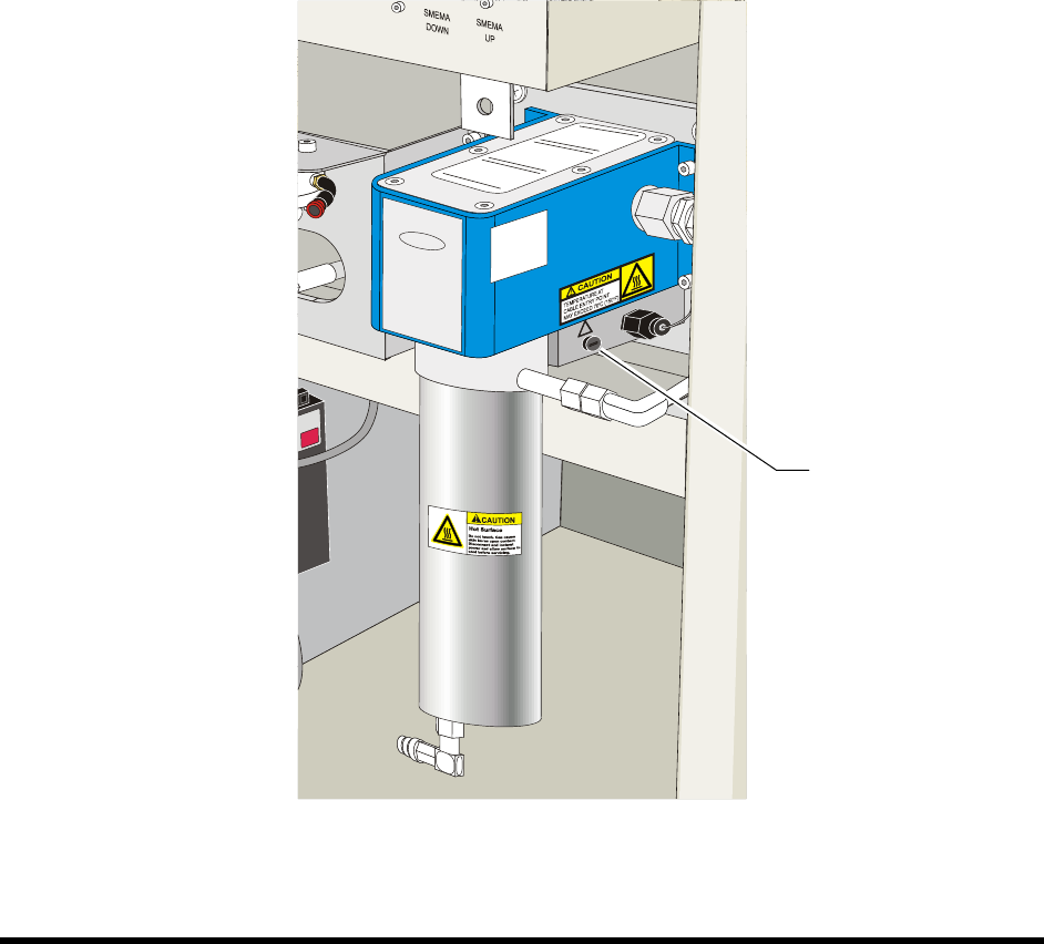
9.10.2 Fluid System Heater Fuse
To replace the Fluid System Heater Fuse:
1. Perform a service shutdown as specified in 2.12 Service Shutdown.
2. With a flat head screwdriver, gently push in and turn the fuse holder counterclockwise until
the head of the fuse holder pops out enough to allow you to grasp it.
3. Pull the fuse holder out of its socket.
4. Remove and discard the damaged fuse.
5. Verify that you will be installing the correct replacement fuse and then insert the new fuse
into the fuse holder.
6. With a flat head screwdriver, simultaneously push and twist the fuse holder clockwise into
the socket until it locks into place.
7. Power on the dispensing system as described in 4.7 Powering on the System.
Figure 9-12 Fluid System Heater
Fuse Location