SL940-Install-Ops-Maintenance-7210918_B.pdf - 第81页
Operation 5-1 5 Operation 5.1 Overvi ew Before operating y our Selec t C oat SL -940E/SL- 941E Series Con formal Coating Sy stem , it may be helpful to fam iliarize yourself w ith the basics of how the system works. This…
4-20 Power-up and Testing
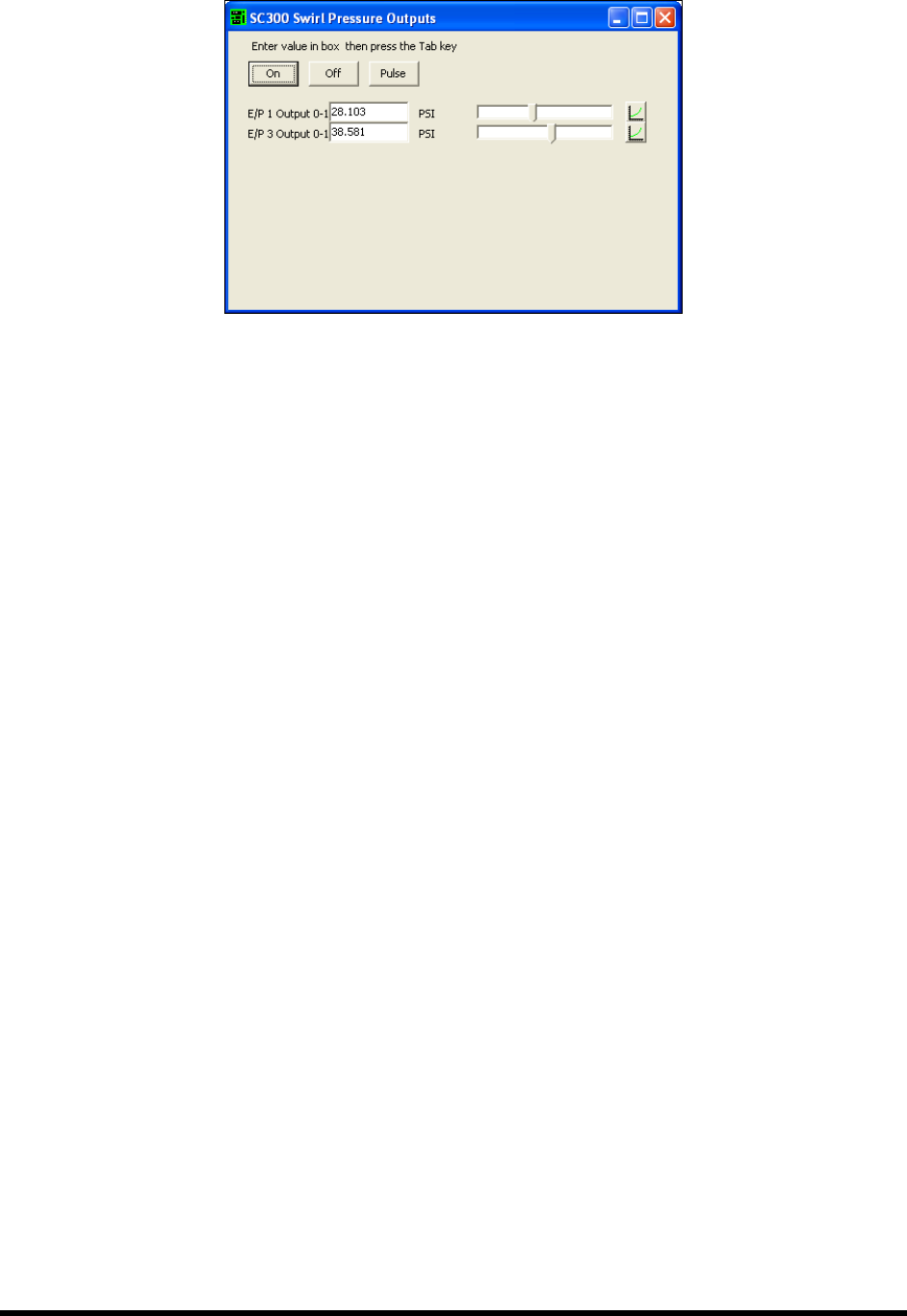
Figure 4-15 Pressure Output Dialog Box
4. Enter a value in the Output field and press the [Tab] key on your keyboard.
As an alternative, you may use the slider bar in the dialog box to adjust the pressure. It
may take several seconds for the pressure to change and a value to appear.
5. Click on the
On button to turn the output on. Click on the Off button to turn it off.
6. Click and hold on the
Pulse button to turn the output on. The output turns off when you
release the button.
4.15.2 Flow Meter
If the system is equipped with a Flow Meter, use the following ECXP command to test functionality.
1. Select
Edit > Edit Mode from the ECXP Operator Screen to access the ECXP Edit Screen.
2. Select
Utilities > Fluid System > Flow Meter Test from the menu bar to test the Flow Meter.
NOTE This option will not appear on the menu unless your system has been configured for a
Flow Meter. For detailed information, refer to the Easy Coat User Guide or the Flow
Monitoring System Owner’s Manual.
4.15.3 Bar Code Scanner
If the system is equipped with a Bar Code Scanner, use the following ECXP command to test
functionality.
1. Select
Edit > Edit Mode from the ECXP Operator Screen to access the ECXP Edit Screen.
2. Select
Utilities > Bar Code Scanner > Trigger Read from the menu bar to scan the bar code
that is currently under the scanner and display the code in a dialog box.
This utility is useful if the bar code label does not include the alphanumeric
representation of the bar code.
3. Click on
Utilities > Bar Code Scanner > Terminal to open a terminal window that enables
you to communicate directly with the scanner.
NOTE This option will not appear on the menu unless your system has been configured for a Bar
Code Scanner. For detailed information, refer to the Easy Coat User Guide.

Operation 5-1
5 Operation
5.1 Overview
Before operating your Select Coat SL-940E/SL-941E Series Conformal Coating System, it may be
helpful to familiarize yourself with the basics of how the system works. This section covers the following
topics:
• Basic System Operation • Daily Routine Procedures
• Conformal Coating • Installing the Coating Applicator
• Easy Coat for Windows XP (ECXP) • Filling the Fluid Reservoir
• Dispensing Operations • Changing Material/Flushing Fluid System
• Conveyor Operations • Focusing the Camera
• Detailed Operation (SL-940E) • Loading a Program
• Positioning the Robot • Running a Program
• Pneumatic Regulators and Gauges • Production Statistics
• System Startup/Shutdown
NOTE In this section, typical SL-940E/SL-941E configurations are considered. However,
operational details may vary with the configuration of your system.
5.2 Safety First
Operation of the SL-940E/SL-941E involves heat, air pressure, electrical power, mechanical devices, and
the use of hazardous materials. It is essential that every person servicing or operating the coating system
fully understands all hazards, risks, and safety precautions. Refer to Section 2 - Safety for additional
information.
5.3 Basic System Operation
The SL-940E/SL-941E is a high-speed, high-accuracy coating system with integrated, closed-loop
process control that ensures superior coating quality. Process parameters are recorded and traceable
through Easy Coat (ECXP) software running on Windows XP operating system. Easy Coat for Windows
XP (ECXP) software controls both the robot movements and the dispensing operation.
The SL-940E has a chain conveyor, which carries the workpiece from an upstream machine, to a
dispensing station where fluid is dispensed, and then delivers the processed workpiece to a downstream
machine. The SL-941E is configured with adjustable tooling rails instead of a conveyor. The adjustable
tooling rail is ready to accept boards with a 3mm or greater edge clearance.
5.4 Conformal Coating
The Select Coat SL-940E/SL-941E Series Conformal Coating System is designed to apply conformal
coating materials with a high level of flexibility and consistency. Conformal coating is a material that is
applied to a circuit board to provide protection from chemical and mechanical damage.
Applying conformal coating is a two-step process. Dispensing the conformal coating is the first step.
After the conformal coating has been applied, it must be cured. The curing method depends on the coating
material. Most materials are cured by heat (infrared), UV (ultraviolet light), or moisture (humidity).

5-2 Operation
5.5 Easy Coat for Windows XP (ECXP)
ECXP is Asymtek's proprietary conformal coating software for use in a Windows XP environment. The
software allows the user to develop program files (.ECW file extension), which contain all the robot
moves and I/O operations necessary to coat the workpiece. Refer to 5.17 Loading a Program and 5.18
Running a Program for detailed instructions on how to load and run a dispensing program.
NOTE A workpiece is defined as a board or substrate (PCB, PWB, etc.) or a carrier (pallet, auer
boat, lead frame, etc.) to be dispensed upon.
5.6 Dispensing Operations
All coating operations take place in a workcell. The workcell contains a robot with a coating applicator
mounted on the robot tool arm and a conveyor or adjustable tooling rails.
5.6.1 Robot Concepts
5.6.1.1 Home
The home position of the robot is a known position within the workspace defined by X, Y, and Z
coordinates. It is located at the front left of the workcell.
5.6.1.2 Robot Motion
Robot moves are specified as coordinates on the X, Y, or Z-axes. If a move combines motion in all three
axes, and the Robot Controller cannot move the robot in the Z-axis at the same time as the X and Y-axes,
then the move is performed (depending on the Safe Z Height setting) as follows:
• If the destination is higher than the starting point, the Z motion is performed first.
• If the destination is lower than the starting point, the Z motion is performed last.
5.6.2 Tool
A tool consists of one of the following: (1) coating applicator and nozzle, (2) teach camera, or (3) laser
pointer for programming.
5.6.2.1 Tool Offset
The tool offset is the X, Y, and Z distance from the robot's lower tooling pin to the tool tip (the end of the
nozzle). Robot position is calculated using the coordinates of the tooling pin plus the offset. Refer to
6.12 Robot Configuration to establish Tool Offsets.
5.6.2.2 Safe Z Height
This is the height below which the tool tip cannot go when moving in the workcell. It prevents the tool tip
from colliding with a board component, a fixture, or the conveyor. The Safe Z Height is set in the ECXP
program. Refer to 6.12 Robot Configuration to set the Safe Z Height.
5.6.3 Fixture
Fixture is defined as the location inside the work area used as a consistent and repeatable point for
positioning and queuing the product that will be coated. Refer to 6.9 Fixture Configuration.