SL940-Install-Ops-Maintenance-7210918_B.pdf - 第57页
Insta llat ion 3-7 4. Place the box l evel between the fron t and r ear conv eyor rai ls along t he Y-axis ( Fi gur e 3-7 ). 5. Observe th e po sition of the bubble within the level’s wi ndow. The bubble should be cent…
3-6 Installation
3.5 Leveling the Coating System
WARNING! CAUTION!
This procedure should only be performed by a trained service technician. The
system should be shutdown for service before performing this procedure. Refer
to 5.11.2.4 Service Shutdown.
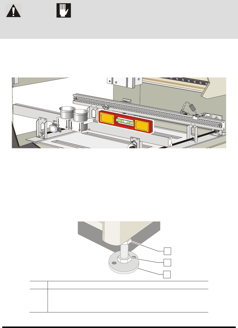
1. Place a box level on the conveyor rail along the X-axis (Figure 3-5).
2. Observe the position of the bubble within the level’s window.
The bubble should be centered, indicating the coating system is level from side-to-side.
Figure 3-5 Leveling the Coating System – X-Axis
3. If necessary, adjust the levelers (Figure 3-6) of the coating system as follows:
a. Loosen the 1 1/2-inch lock nut on the leveler if necessary.
b. Turn the 1 1/2-inch post nut in the desired direction until the level’s bubble is centered,
indicating that the system is level from side-to-side.
Turning the post nut clockwise raises the coating system. Turning the post nut
counterclockwise lowers the coating system.
Item Description
1 Lock Nut
2 Post Nut
3 Leveler
Figure 3-6 Coating System Levelers (Feet)
1
2
3
Installation 3-7
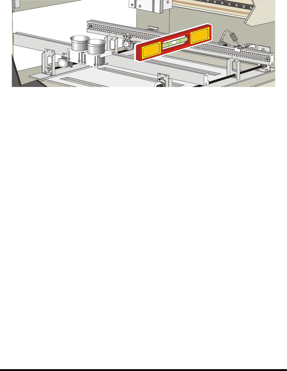
4. Place the box level between the front and rear conveyor rails along the Y-axis (Figure 3-7).
5. Observe the position of the bubble within the level’s window.
The bubble should be centered, indicating coating system is level from front-to-back.
Figure 3-7 Leveling the Coating System – Y-Axis
6. If necessary, adjust the levelers (Figure 3-6) of the coating system as follows:
a. If necessary, loosen the 1 1/2-inch lock nut on the leveler.
b. Turn the 1 1/2-inch post nut in the desired direction until the level’s bubble is centered,
indicating that the system is level from front-to-back.
Turning the post nut clockwise raises the coating system. Turning the post nut
counterclockwise lowers the coating system.
7. Check the system for stability by pressing up and down on one of the top corners of the
coating system. If one leveler is lower or higher than the others, the coating system will rock
back and forth. Adjust the levelers so that they are all bearing the weight equally.
8. Re-level the coating system from side-to-side and from front-to-back, if necessary.
3-8 Installation
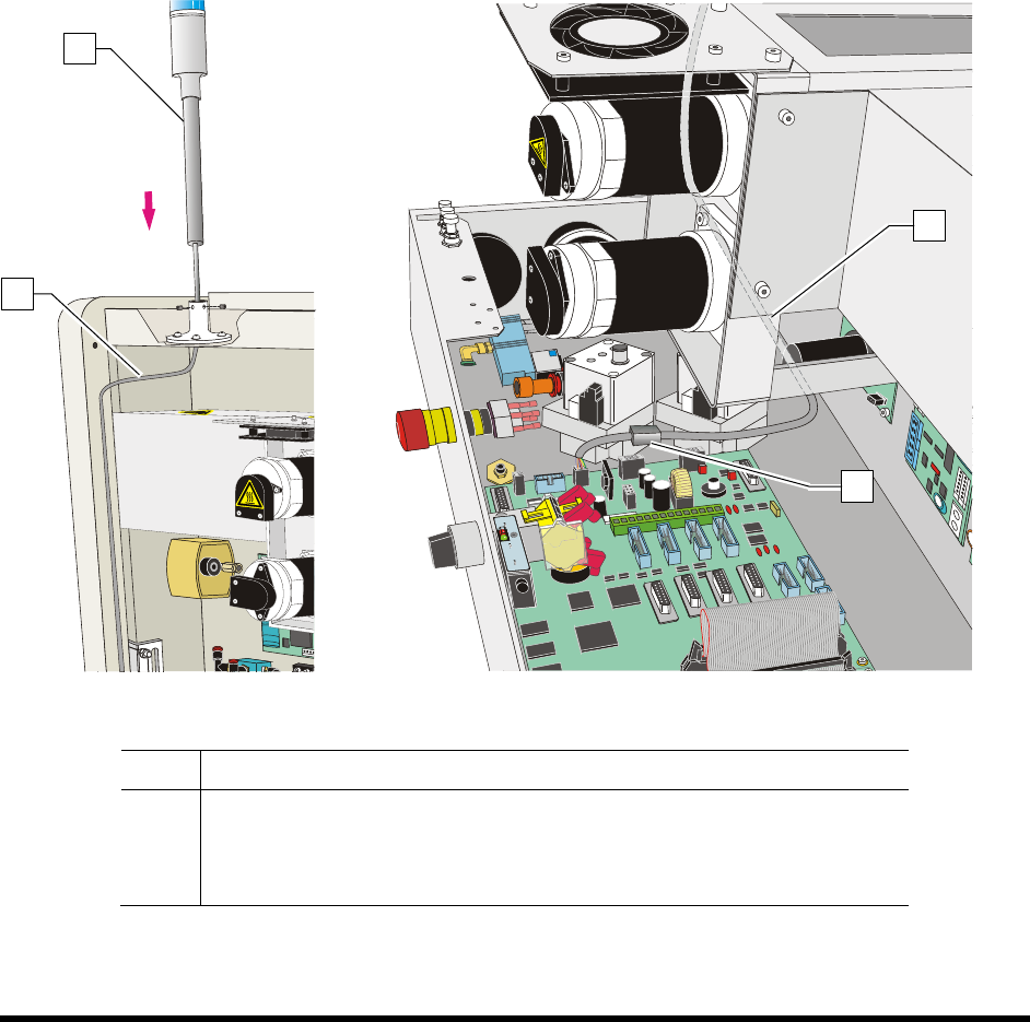
3.6 Installing the Light Beacon
1. Loosen the five (5) screws on the electronics/pneumatics cover and remove it.
2. Remove the ferrite bead from the cable.
3. Feed the electrical cable on the light beacon through the top of the light beacon base
(Figure 3-8A).
4. Set the light beacon into the base and tighten the set screws.
5. Route the electrical cable as shown in Figure 3-8A and Figure 3-8B.
6. Make the beacon electrical connections (Figure 3-8B).
7. Replace the ferrite bead.
8. Replace the electronics/pneumatics cover and tighten the screws that hold the panels in place.
Figure 3-8A
Figure 3-8B
Item Description
1 Beacon
2 Electrical Cable
3 Ferrite Bead
Figure 3-8 Installing the Light Beacon
1
2
2
3