SL940-Install-Ops-Maintenance-7210918_B.pdf - 第133页
Maintenance 7-3 7.6 Cleaning t he Spill Pa n The Spill Pan is l ocated in the front cabinet a nd c apt ur es fluid spills and overspray. The s pill pan should be cleane d reg ularly and i s rem ov able for ease of cleani…
7-2 Maintenance
7.5 Routine Maintenance Procedures
WARNING! CAUTION!
Before performing any of the maintenance procedures in this section, perform a
service shutdown described in 5.11.2.4 Service Shutdown.
NOTE The following maintenance procedures are for the SL-940E/SL-941E Series Conformal
Coating Systems only. Refer to the appropriate manual for recommended maintenance
procedures for your specific coating applicator.
Routine maintenance procedures and required intervals are listed in Table 7-1. It is also recommended
that you follow all procedures listed in 5.12 Daily Routine Procedures.
Table 7-1 Routine Maintenance Procedures
Task Frequency Instructions
Clean Dispensing Area Daily
Remove spilled fluids with the manufacturer’s recommended
solvent and a soft cloth. Remove any foreign objects from the
dispensing area and ventilation holes.
NOTE Make sure the coating system ventilation is
ON during handling and cleanup of all
materials used with the coating system. DO
NOT cover ventilation holes.
Clean Spill Pan Daily
See 7.6 Cleaning the Spill Pan.
Clean Fluid Filter Weekly
Replace as necessary. Refer to 7.8 Cleaning the Fluid Filter.
Drain Water Trap Weekly
Check the water level in the water trap and empty if full. See
7.7 Emptying the Water Trap.
Check Conveyor Weekly
Check conveyor guards for alignment and security. Inspect
conveyor chains for proper tension.
Inspect Hardware Weekly
Inspect coating system for broken, loose, worn, or missing
hardware. Replace or repair as necessary.
Inspect Electrical And
Pneumatic Lines
Weekly
Inspect coating system for broken, loose, or frayed electrical
and pneumatic lines. Replace as necessary.
Check Air Cylinders Monthly Check for leakage.
Lubricate the Cables and
Linear Guides
Every three
months
See 7.10 Lubricating the Cables and Linear Guides.
Tension Mechanical Drive
Cables
Every 6-12
months
See 7.11 Tensioning the Cables.
Empty Purge Cups As Needed
Empty and clean purge cups. Follow MSDS
recommendations for the proper handling and disposal of all
materials.
Refill Solvent Cups As Needed Refill as needed.
Clean Camera Lens (if
applicable
As Needed Use the cleaning kit provided.
Tension Conveyor Chains As Needed
See 7.12 Tensioning the Conveyor Chains.
Replace Conveyor
Chains
As Needed
See 9.8 Replacing Conveyor Chains.
Maintenance 7-3
7.6 Cleaning the Spill Pan
The Spill Pan is located in the front cabinet and captures fluid spills and overspray. The spill pan should
be cleaned regularly and is removable for ease of cleaning.
WARNING! CAUTION!
Follow MSDS recommendations for the proper handling and disposal of all
materials when cleaning the spill pan. Always wear appropriate personal
protective equipment (PPE) as recommended by facility safety practices and the
material manufacturer’s MSDS.
NOTE Make sure the ventilation is ON while cleaning the spill pan.
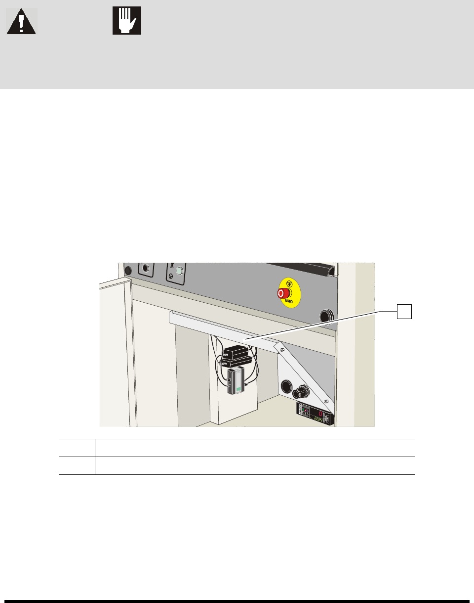
1. Slide the spill pan from the lower front cabinet.
2. Thoroughly clean the pan with the solvent recommended by the fluid manufacturer.
3. Slide the spill pan all the way in.
The spill pan is interlocked for safety. If the spill pan is not pushed in properly, the
coating system will not start.
NOTE Keep the spill pan free of debris. DO NOT use the spill pan for storage.
Item Description
1 Spill Pan
Figure 7-1 Spill Pan
1
7-4 Maintenance
7.7 Emptying the Water Trap
Moisture from the outside air can condense in the pneumatic system. The water trap collects this
condensed moisture. You must empty it weekly or whenever it is full.
To empty the water trap:
1. Locate the water trap (Figure 7-2) at the rear of the system.
2. Disconnect the facility air supply from the main air inlet.
3. Hold a container under the water trap to catch the water.
4. Using your finger, push the water drain knob at the bottom of the assembly.
5. Reconnect the facility air supply to the main air inlet.
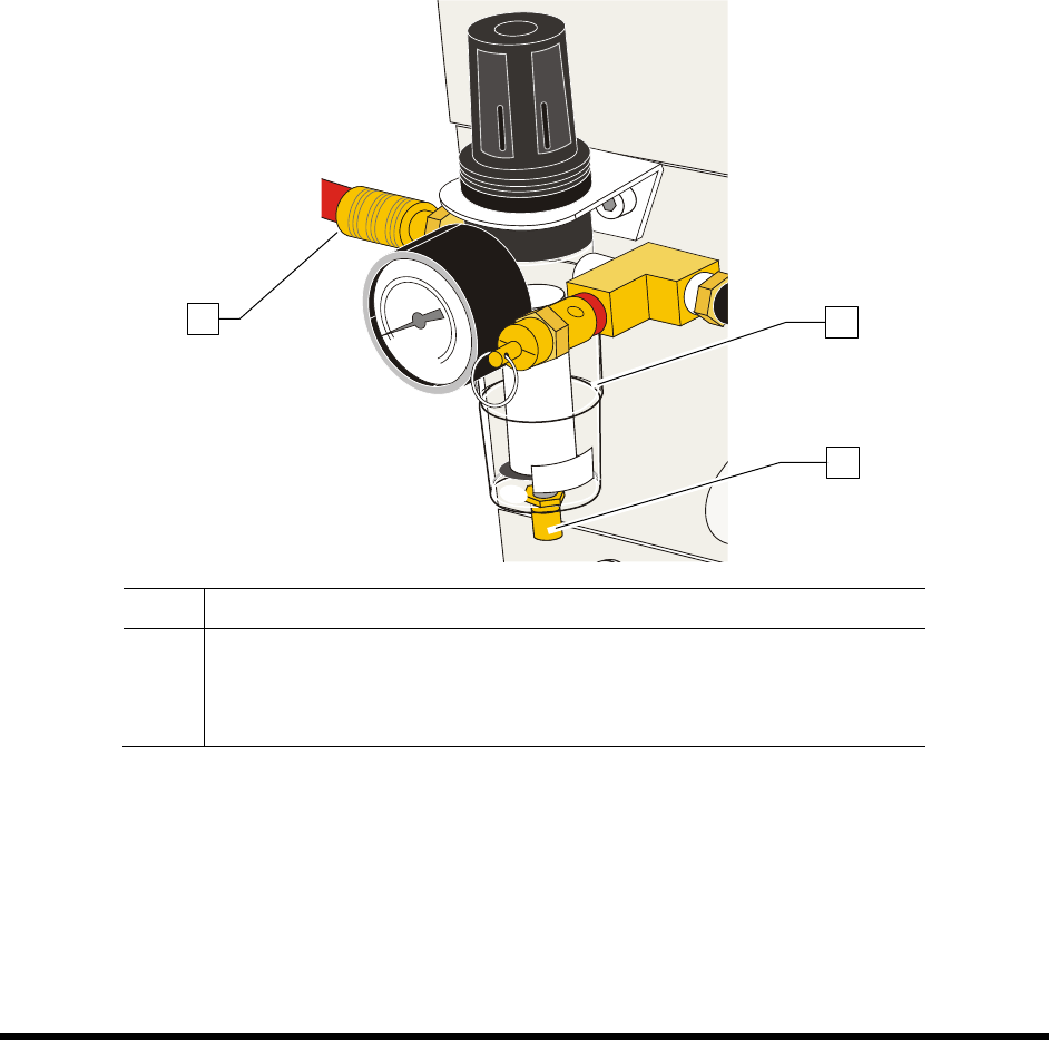
Item Description
1 Water Trap
2 Drain Knob
3 Main Air Inlet
Figure 7-2 Water Trap
1
2
3