SL940-Install-Ops-Maintenance-7210918_B.pdf - 第87页
Operation 5-7 5.10 Pneumat ic Regulator s and Gauges The SL -940E/SL- 941E Series Confor mal Coating System s have the follow ing pneum atic regulators and gaug es: • Ma in A ir Regul a t or and G auge • Reservoi r Press…
5-6 Operation
5.9 Positioning the Robot
If necessary, the operator can use the ECXP to reposition the robot in the X-, Y-, and Z-axes.
To move the robot using the arrow keys:
1. Start the ECXP software. See 4.9 Starting Easy Coat for Windows (ECXP).
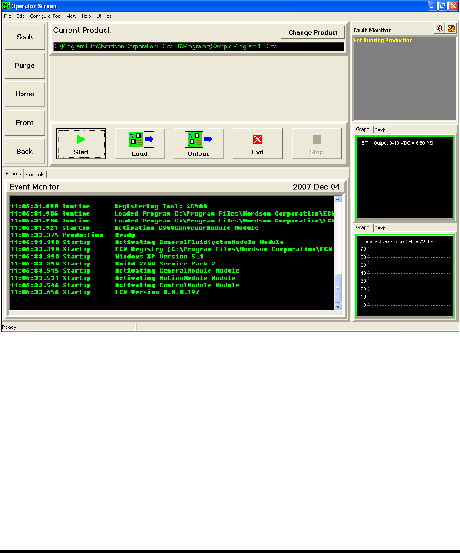
The Operator Screen opens (Figure 5-3).
Figure 5-3 Moving the Robot
2. Use the keys on the computer keypad to move the robot as follows:
a. XY-Axis (Slow) – Hold down <Ctrl> and press the right and left arrow keys for X-axis
movement and up and down arrows for Y-axis movement.
b. XY-Axis (Fast) – Hold down <Ctrl> + <Shift> and press the right and left arrow keys for
X-axis movement and up and down arrows for Y-axis movement.
c. Z-Axis (Slow) – Hold Down <Ctrl> + <Z> and then press up or down arrow keys for
desired Z-axis movement.
d. Z-Axis (Fast) – Hold Down <Ctrl> + <Shift> + <Z> and press up or down arrow keys for
desired Z-axis movement.
Operation 5-7
5.10 Pneumatic Regulators and Gauges
The SL-940E/SL-941E Series Conformal Coating Systems have the following pneumatic regulators and
gauges:
• Main Air Regulator and Gauge
• Reservoir Pressure Regulator and Gauge
• Fluid Pressure Regulator and Gauge
• Conveyor Air Regulator and Gauge
The Main Air Regulator is located at the rear of the system (Figure 5-4). The Reservoir Pressure
Regulator is located inside the front cabinet (Figure 5-5). Fluid pressure is controlled through the ECXP
software (Figure 5-6).
WARNING! CAUTION!
Make sure the Safety Interlock Recovery Light located on the Front Panel is ON
before you access the inside of the dispensing area. When the light is OFF,
accessing the inside of the dispensing area will cause a non-recoverable
interlock condition to occur. Refer to Section 2 - Safety for additional information.
Recommended pressure settings are provided in Table 5-1. See detailed adjustment instructions following
descriptions in this section. See 4.12 Pneumatics for other regulator adjustments.
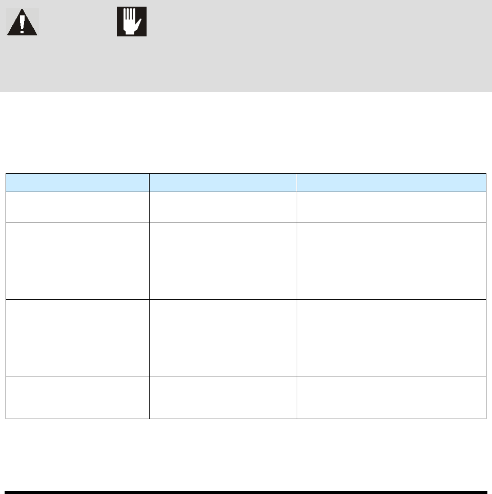
Table 5-1 Recommended Pressure Settings
Device Recommended Pressure Comments
Main Air Pressure Regulator 551 kPa (80 psi)
Facility pressure is 586 to 620 kPa
(85 to 90 psi).
Reservoir Air Pressure
Regulator
206 to 276 kPa (30 to 40 psi)
Recommended pressure depends on
fluid being dispensed and coating
applicator being used. Refer to the
Installation and Operations manual
applicable to the coating applicator on
your system.
Fluid Pressure 69 to 414 kPa (10 to 60 psi)
Recommended pressure depends on
fluid being dispensed and coating
applicator being used. Refer to the
Installation and Operations manual
applicable to the coating applicator on
your system.
Conveyor Air Regulator and
Gauge
276 kPa (40 psi)
The Conveyor Air Regulator and Gauge
is used to adjust pressure for the
conveyor stop pins and board pins.
NOTE Some coating applicators need a minimum of 345 to 414 kPa (50-60 psi) for optimum
performance.
5-8 Operation
5.10.1 Main Air Regulator and Gauge
The Main Air Inlet provides regulated air pressure to the coating system from your facility air source.
You can adjust the main air pressure with the Main Air Regulator. The recommended pressure from the
facility air supply to the coating system is 85 to 90 psi (586 to 620 kPa).
To adjust the main air pressure:
1. Verify that the facility air supply is connected to the Main Air Inlet.
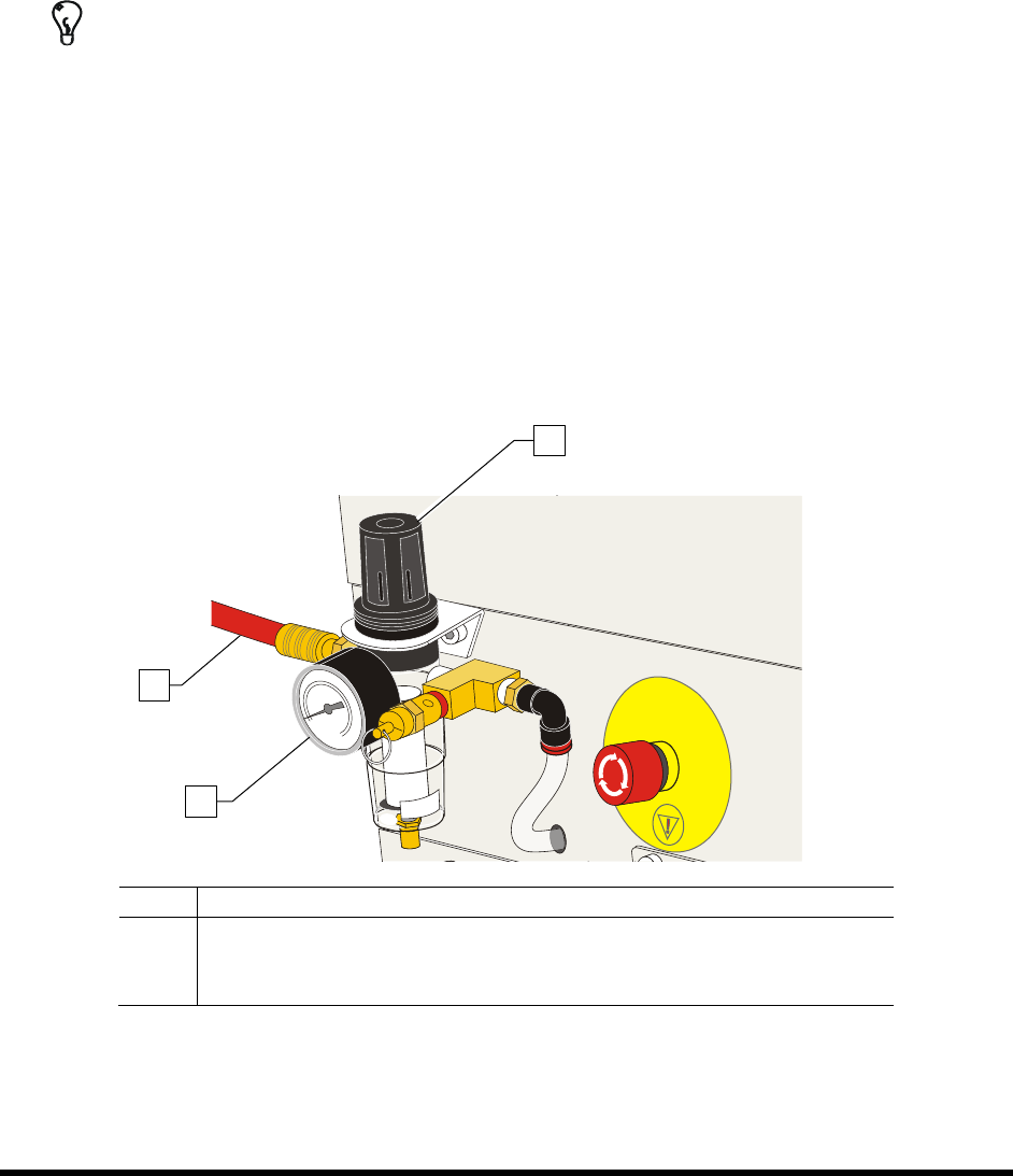
2. Locate the Main Air Regulator at the rear of the coating system (Figure 5-4).
TIP For accurate pressure adjustment, lower the pressure below the desired level and then
increase to the desired pressure.
3. Rotate the Main Air Regulator counterclockwise until the Main Air Gauge registers 0 psi.
4. Rotate it clockwise until the Main Air Gauge registers 85 to 90 psi (586 to 620 kPa).
If the Main Air Gauge fails to register pressure, verify that the coating system is
connected to the facility air source.
If there is an air leak, identify the source, shut off the facility air, and fix the leak before
proceeding.
NOTE The regulator assembly is equipped with a relief valve to protect the system components.
Increasing the pressure above 95 psi (655 kPa) may trigger the relief valve. If so, reduce
the air pressure below 95 psi.
Item
Description
1 Main Air Regulator
2 Main Air Gauge
3 Main Air Inlet
Figure 5-4 Adjusting Main Air Pressure
3
2
1