SL940-Install-Ops-Maintenance-7210918_B.pdf - 第64页
4-4 Powe r - up a nd Tes ti ng Item Descripti on 1 Exhaust Vent 2 Main Air In let 3 Main Po wer Circ uit Bre aker 4 Main Po wer Cord Figure 4-1 C onnec ting t he Facil ities Po wer and Air Su pply (10 A Power Manager s h…
Power-up and Testing 4-3
4.6 Connecting Power and Air Supply
WARNING! CAUTION!
Make sure that your facility meets all requirements listed in Section 10 -
Specifications. Failure to meet these requirements could result in serious bodily
injury to personnel and damage to the coating system.
CAUTION! This procedure should only be performed by a trained service technician.
Tools and Materials Needed:
• Main Power Cable
• Quick Release Air Hose Nozzle
To connect the facilities power and air supply:
CAUTION! Switch the Main Circuit Breaker to the OFF (0) position before proceeding.
1. Unpack the main power cable and remove all packing material including plastic wrappers and
tie wraps.
2. Plug the female end of the power cable into the main power inlet on the lower left side of
the coating system. Plug the male end of the power cable into the facility power source
(Figure 4-1).
3. Locate and attach the quick disconnect air nozzle to the facility air hose.
4. Connect the facility air hose to the main air inlet connector on the back right side of the
coating system.
5. Connect the facility exhaust ventilation system ductwork to the exhaust vent duct
(Figure 4-1).
6. Adjust airflow to a minimum of 600 scfm with the front door closed.
4-4 Power-up and Testing
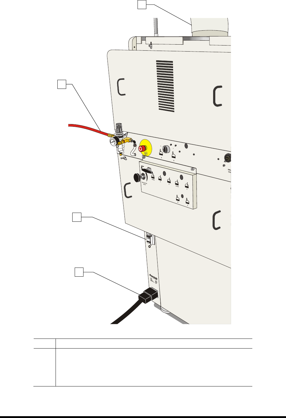
Item Description
1 Exhaust Vent
2 Main Air Inlet
3 Main Power Circuit Breaker
4 Main Power Cord
Figure 4-1 Connecting the Facilities Power and Air Supply (10A Power Manager shown)
2
3
4
1
Power-up and Testing 4-5
4.7 Powering On the System
To power on the coating system:
1. Verify that the main power cord is connected to the main power inlet and the facility
power source (Figure 4-1).
2. Verify that the facility air hose is connected to the main air inlet (Figure 4-1).
3. Verify that the facility exhaust ventilation system ductwork is connected to the Exhaust Vent
Duct (Figure 4-1).
4. Turn the main circuit breaker to the
ON (I) position (Figure 4-1).
5. Check the EMO buttons to see if they have been activated. If one has been activated,
deactivate it by turning the red knob clockwise until the knob pops out (Figure 4-2).
6. Make sure the interlock signal is not interrupted. Close the coating system hood if applicable.
7. Verify the spill pan in the lower front cabinet is all the way in (Figure 1-7).
8. Turn the laptop computer power button
ON (I).
9. Press the
ON (l) button on the front panel (Figure 4-2).
NOTE During power up, the green start button on the front panel will blink. The coating system
will turn on after an approximate 60-second vent air time delay to ventilate any solvents
in the dispense area. When the system is ready, the green start button will display a solid
light and the light beacon will be green,
The coating system should be in a powered-up state.
The system computer should begin the boot up sequence.
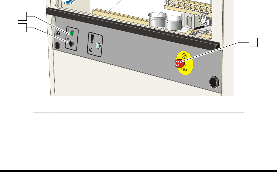
Item Description
1 Start Button
2 Stop Button
3 EMO
Figure 4-2 Front Panel Buttons
1
2
3