SL940-Install-Ops-Maintenance-7210918_B.pdf - 第60页
3- 10 Insta llat ion 3.8 Installi ng the Optional Genie Ca mera NOTE The Geni e Fram ework Software is instal led at the factory prior to shippi ng. To connec t the ca mera: 1. Connect a power supply to the Genie cam e…
Installation 3-9
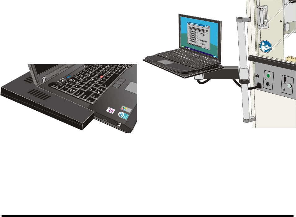
3.7 Installing the Laptop Computer
NOTE The laptop computer is shipped from the factory fully charged
1. Remove the laptop computer from its packaging.
2. Remove the keys from the lock and give them to the person responsible for the machine.
The keys are used to lock the laptop computer to the dispensing system tray.
3. Move the laptop tray arm bracket on the dispensing system so that the laptop tray is facing
forward.
4. Attach the USB and Network cables and grounding wire attachment to their respective ports
on the computer.
5. Attach the power cable to the rear of the computer.
NOTE The laptop is adhered to the tray with a hook and loop fastener. Align the laptop
computer before placing it on the tray.
6. With the laptop lid closed, align the computer with the covers such that no gaps exist on the
left hand side or the back edge.
7. Gently press the laptop onto the base.
8. Attach the locking cable to the laptop.
Figure 3-9 Aligning the Computer to the Tray Figure 3-10 Laptop Computer Installed
3-10 Installation
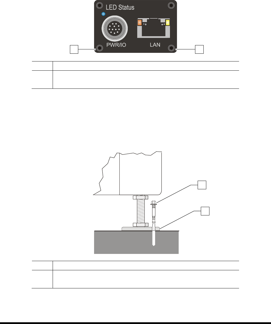
3.8 Installing the Optional Genie Camera
NOTE The Genie Framework Software is installed at the factory prior to shipping.
To connect the camera:
1. Connect a power supply to the Genie camera (Figure 3-11).
2. Connect an RJ5 Ethernet cable from the camera to the laptop computer.
Item Description
1 Power Connection
2 Ethernet Connection
Figure 3-11 Camera (Rear View)
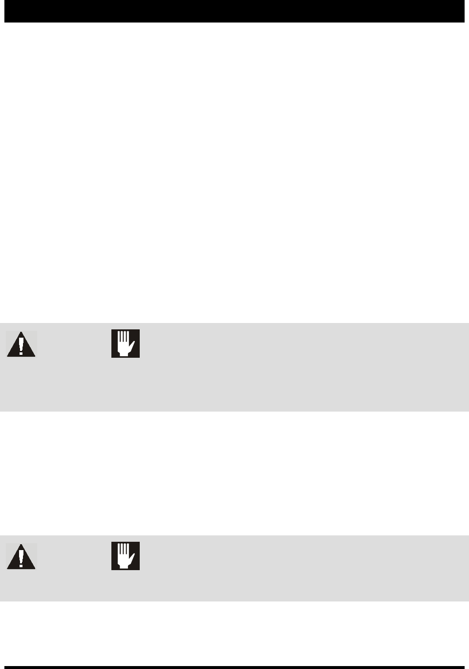
3.9 Anchoring the Coating System
To prevent movement that could cause injury to personnel and damage to the coating system and facility,
each coating system leveler (foot) should be anchored to the floor with one wedge anchor (Figure 3-12).
Refer to Facility Specification SL94XE (P/N 7218847).
Item Description
1 Wedge Anchor
2 Leveler
Figure 3-12 Anchoring the Coating System
NOTE You may also use the shipping brackets to anchor the coating system.
1
2
2
1
Power-up and Testing 4-1
4 Power-up and Testing
4.1 Overview
This section describes the power-up and testing procedures for making sure that all system components
are functioning and communicating properly. This section covers the following topics:
•
Pneumatic Connections
•
Testing the System
•
Electrical Connections
•
Robot/Conveyor I/O
•
Exhaust Connection •
Pneumatics
•
Connecting Power and Air Supply
•
Robot (Dispensing Head) Function
•
Powering On the System •
Conveyor Function
•
Camera States
•
Coating System Options
• Starting Easy Coat for Windows (ECXP)
4.2 Safety First
Operation of your SL-940E/SL-941E Series Conformal Coating System involves heat, air pressure,
electrical power, mechanical devices, and the use of hazardous materials. It is essential that every person
servicing or operating the coating system fully understands all hazards, risks, and safety precautions.
Refer to Section 2 - Safety for additional information.
WARNING! CAUTION!
To ensure optimal performance and safety, it is necessary to install the coating
system in a facility that meets the necessary requirements listed in Section 10 -
Specifications. If you have any questions, please contact Asymtek Technical
Support.
4.3 Pneumatic Connections
Depending on system configuration, the SL-940E/SL-941E requires 85 to 90 psi (586 to 620 kPa) up to
0.34 m
3
/min (12 SCFM) max. of clean, dry air delivered through a 12.7 mm (0.5 inch) pipe or hose.
Connect the air supply to the ¼ -inch NPT quick-disconnect fitting at the Main Air Inlet (Figure 4-1).
NOTE The maximum air supply pressure should not exceed 90 psi (620 kPa). The system is
equipped with a 100 psi relief valve.
WARNING! CAUTION!
All system pneumatic connections should be checked before the main air
is connected.
Refer to Appendix B for SL-940E/SL-941E pneumatic diagrams.