SL940-Install-Ops-Maintenance-7210918_B.pdf - 第158页
9- 10 Parts Replacement 9.10.2 Fluid Sy stem Heater F use To replace the F luid Sys tem Heat er Fus e: 1. Perform a service shutdow n as sp ecif ied in 2.12 Ser vice Shutdown . 2. With a flat h ead scr ewdriv er , gently…
Parts Replacement 9-9
9.10 Replacing Fuses
If your Select Coat SL-940E/SL-941E is equipped with a heated fluid system, there are two replaceable
fuses. See Table 9-1.
CAUTION! Always replace fuses with fuses of identical rating and size. Failure to do so may
not protect components from damage.
9.10.1 Replacement Fuses
Table 9-1 Replacement Fuses
Part Number Qty. Description Location
55-5391 1 FUSE, 4A, 5X20MM, TIME LAG Fluid System Heater
Tools and Materials Needed
•
ESD Grounding Strap
•
Replacement Fuse (see Table 9-1)
• Small Flat Head Screwdriver* • Phillips Screwdriver*
WARNING! CAUTION!
Fuse replacement should be performed by a trained service technician only.
9-10 Parts Replacement
9.10.2 Fluid System Heater Fuse
To replace the Fluid System Heater Fuse:
1. Perform a service shutdown as specified in 2.12 Service Shutdown.
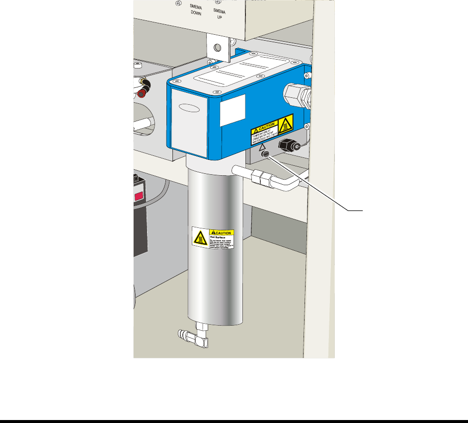
2. With a flat head screwdriver, gently push in and turn the fuse holder counterclockwise until
the head of the fuse holder pops out enough to allow you to grasp it.
3. Pull the fuse holder out of its socket.
4. Remove and discard the damaged fuse.
5. Verify that you will be installing the correct replacement fuse and then insert the new fuse
into the fuse holder.
6. With a flat head screwdriver, simultaneously push and twist the fuse holder clockwise into
the socket until it locks into place.
7. Power on the dispensing system as described in 4.7 Powering on the System.
Figure 9-12 Fluid System Heater
Fuse Location
Specifications 10-1
10 Specifications
10.1 Overview
Select Coat SL-940E/SL-941E Series Conformal Coating System facility requirements and specifications
are listed in Table 10-1 to Table 10-3. These specifications are intended as a convenient reference for
installation, system relocation, planning and operation. Meeting the requirements will ensure reliable
operation and safety of the coating system.
WARNING! CAUTION!
To ensure optimal performance and safety, it is necessary to install the coating
system in a facility that meets the requirements listed in Section 10 -
Specifications. If you have any questions, please contact Asymtek Technical
Support.
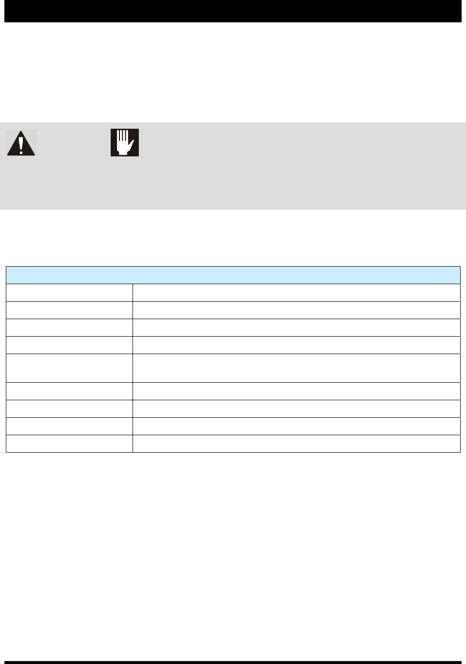
10.2 Facility Requirements
Table 10-1 Facility Requirements
Facility Requirements
System Footprint See Facilities Specification SL-94XE(P/N 7218847)
System Weight 426 Kg (940 lb. max)
Air Supply 620 kPa (90 psi. 6.2 Bar), up to 0.34 m
3
/min (12 SCFM)
Minimum Ventilation Rate 17 m
3
/min @ 25.4 mm water column (600 SCFM @ 1.0 in. water column)
Nitrogen Supply
410 kPa (60 psi, 4.1 Bar) @ 0.014 m
3
/min (0.5 SCFM); required for
moisture-sensitive materials only
Main Power Supply 200/240 VAC 50/60 Hz, 10A
Ambient Air Temperature 5-50 °C
Relative Humidity < 90% non-condensing
Altitude 1609 meters