SL940-Install-Ops-Maintenance-7210918_B.pdf - 第52页
3-2 Inst allat ion To uncrate and place the coat ing sys tem : 1. Check the “Tip & Tell” and "Shockwatch" d evices, both on t he ou tside o f the sh ipping crate and on the coating system , to m ake sure th…

Installation 3-1
3 Installation
3.1 Overview
This section describes installation procedures for the Select Coat SL-940E/SL-941E Series Conformal
Coating System and covers the following topics:
• Uncrating and Placing the Coating System
• Unpacking the Coating Area
• Leveling the Coating System
• Installing the Light Beacon
• Installing the Laptop Computer
• Installing the Optional Genie Camera
• Anchoring the Coating System
3.2 Safety First
Operation of your SL-940E/SL-941E Series Conformal Coating System involves heat, air pressure,
electrical power, mechanical devices, and the use of hazardous materials. It is essential that every person
servicing or operating the coating system fully understands all hazards, risks, and safety precautions.
Refer to Section 2 - Safety for additional information.
WARNING! CAUTION!
To ensure optimal performance and safety, it is necessary to install the coating
system in a facility that meets the necessary requirements listed in Section 10 -
Specifications. If you have any questions, please contact Asymtek Technical
Support.
3.3 Uncrating and Placing the Coating System
Tools and Materials Needed:
•
1/2 inch wrench
•
Band Cutter
•
9/16 inch wrench
•
Phillips Screwdriver (included in tool kit)
•
Personal Protective Equipment •
1 ½-inch wrench (included in tool kit)
•
Hammer
•
Forklift
•
Flat Bar •
Level
WARNING! CAUTION!
Installation procedures should only be performed by a trained service technician.
3-2 Installation
To uncrate and place the coating system:
1. Check the “Tip & Tell” and "Shockwatch" devices, both on the outside of the shipping crate
and on the coating system, to make sure that the coating system has not been dropped or
tipped. If any of these devices has been activated, contact Asymtek.
2. Locate and remove the envelope on the outside of the shipping crate. Open the envelope and
locate the shipping list.
As you unpack each item inside of the box, identify the item, locate it on the shipping list,
and place a checkmark next to the item.
3. Referring to the uncrating instruction sheet, use the flat bar and hammer to remove the lid and
sides of the crate.
WARNING! CAUTION!
Personnel should wear gloves and safety glasses while removing the top and
sides of the crate. Sufficient personnel should be used to lift and control the crate
to prevent serious injury to personnel or damage to the coating system.
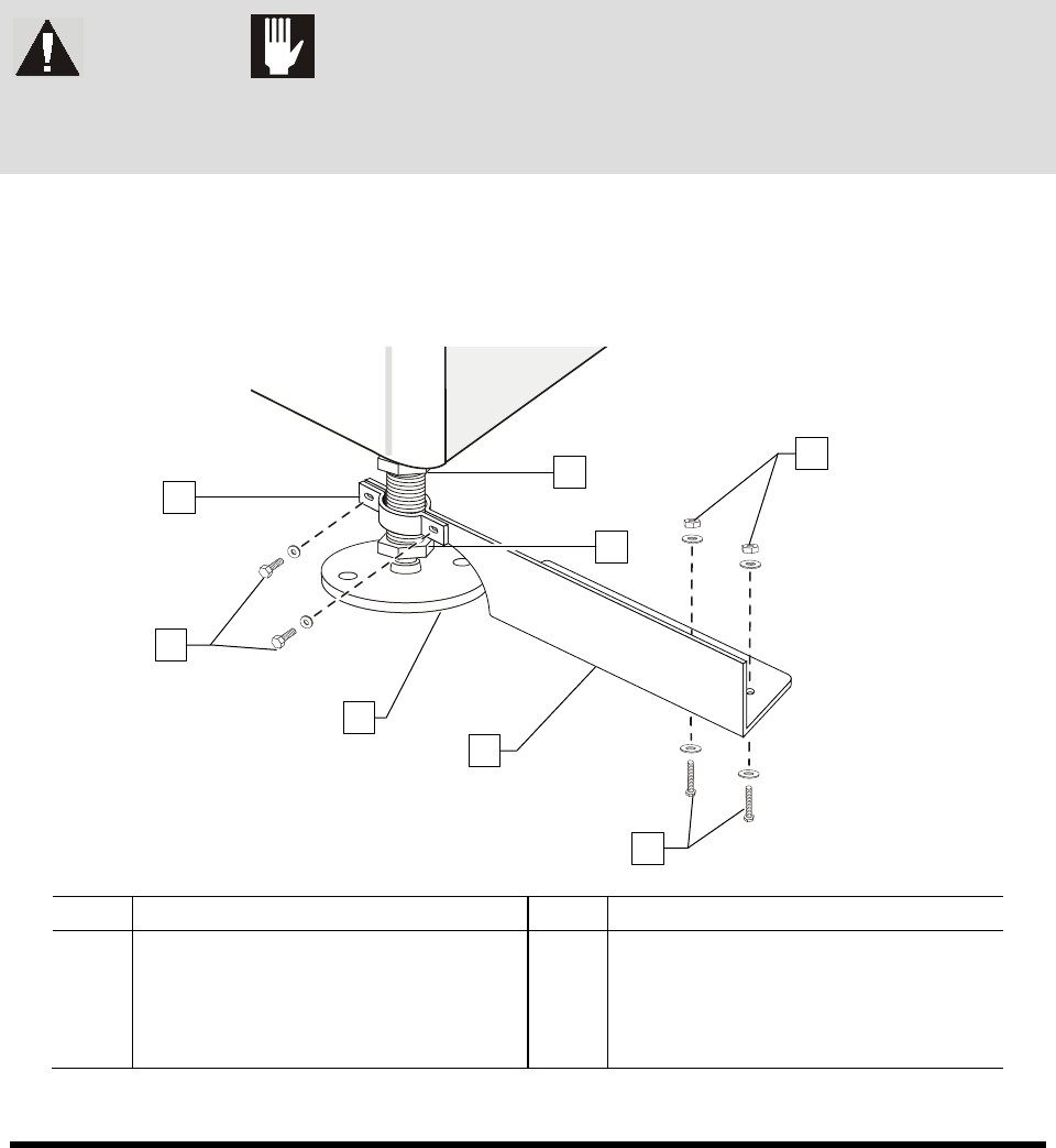
4. Remove the four machine-to-crate shipping brackets attached to the pallet using a 1/2-inch
wrench and 9/16-inch wrench (not provided).
5. Remove the two 1/2-inch hex head screws clamping the four shipping brackets to the
levelers.
Item Description Item Description
1 Foot Restraint Bracket 5 Lag Bolts and Washers
2 Hex Head Screws and Washers 6 Hex Nuts and Washers
3 Leveler (foot) 7 Post Nut
4 Machine-to-Crate Shipping Bracket 8 Lock Nut
Figure 3-1 Removing the Shipping Brackets
1
2
3
4
5
6
8
7
Installation 3-3
6. When the four shipping brackets have been removed, slide the forklift forks under the front of
the coating system between the levelers (feet). Use the forklift to gently lift the coating
system off of the crate.
NOTE You may use the shipping crate for future shipping purposes or dispose of according to
local regulations. Save the shipping brackets. They can be used later for seismically
securing the coating system. See 3.9 Anchoring the Coating System or Facility
Specification SL94XE (P/N 7218847).
7. Move the coating system over the location where it will be installed
8. Slowly lower the forklift until the coating system conveyor rail is at the approximate height
of the mating upstream and downstream equipment.
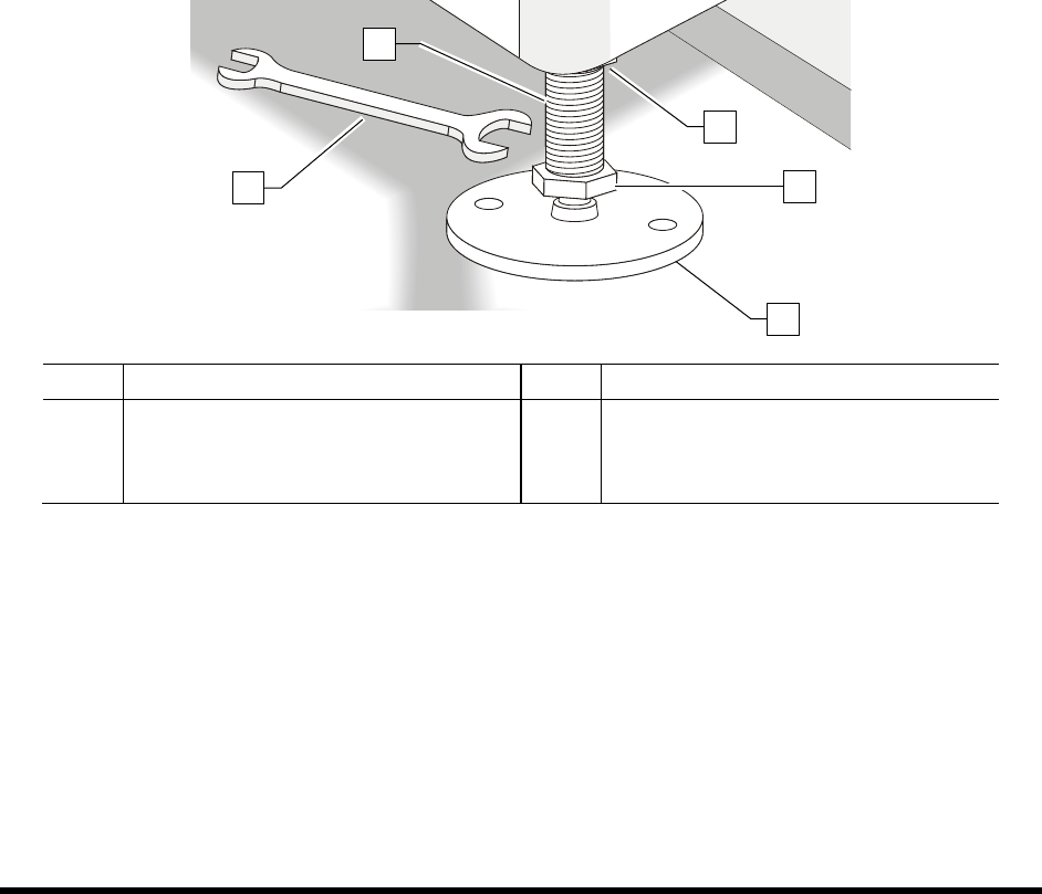
9. Raise or lower each leveler (foot) as follows until they all touch the floor:
a. Loosen the 1 ½ inch lock nut on the leveler. See Figure 3-2.
b. Adjust the 1 ½ inch post nut to raise or lower each leveler as required.
Turning the post nut clockwise lowers the leveler. Turning the post nut
counterclockwise raises the leveler.
c. Tighten the lock nut.
Item Description Item Description
1 Post 4 Post Nut
2 1 1/2-inch Wrench 5 Lock Nut
3 Leveler (foot)
Figure 3-2 Adjusting the Levelers
10. Remove bag and plastic wrap from the machine.
NOTE Location of packaging materials to be removed is indicated by the presence of
red warning tags.
11. Remove all shrink-wrap and other packing material from the perimeter of the coating system.
12. Remove all perimeter packaging material from the dispensing area.
NOTE Remove all shrink wrap and packing foam from the system prior to moving it to
a clean room. If necessary, clean the system thoroughly.
1
2
3
4
5