SL940-Install-Ops-Maintenance-7210918_B.pdf - 第120页
6- 12 Configuration a nd C haracte rization 4. Install the nozzle used t o configure the too l on the coating applicator to teach the Z-coordinate. See Figur e 6-12 for c oor dina t e l oca ti on. a. To teach the Z- coor…
Configuration and Characterization 6-11
To configure a fixture:
NOTE Before configuring the fixture, you must configure the Tool Offsets. Refer to 6.7 Tool
Configuration for detailed instructions.
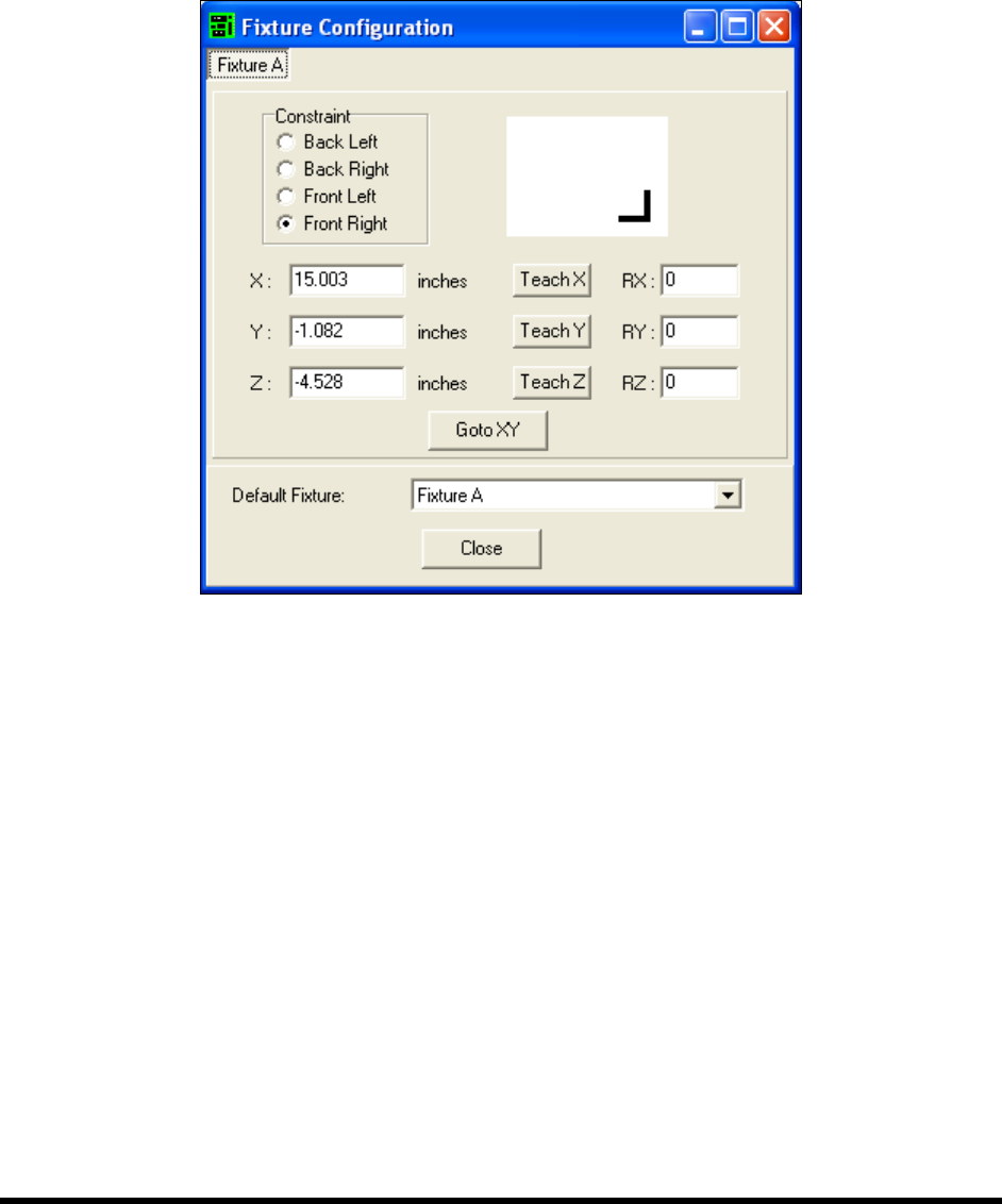
1. To configure a fixture, click on
Configure > Fixtures from the ECXP Edit Screen.
The Fixture Configuration dialog box shown in Figure 6-11 opens.
Figure 6-11 ECXP Fixture Configuration
2. Click on the tab for the fixture you are configuring.
There will be a separate tab for each fixture configured in ECXP.
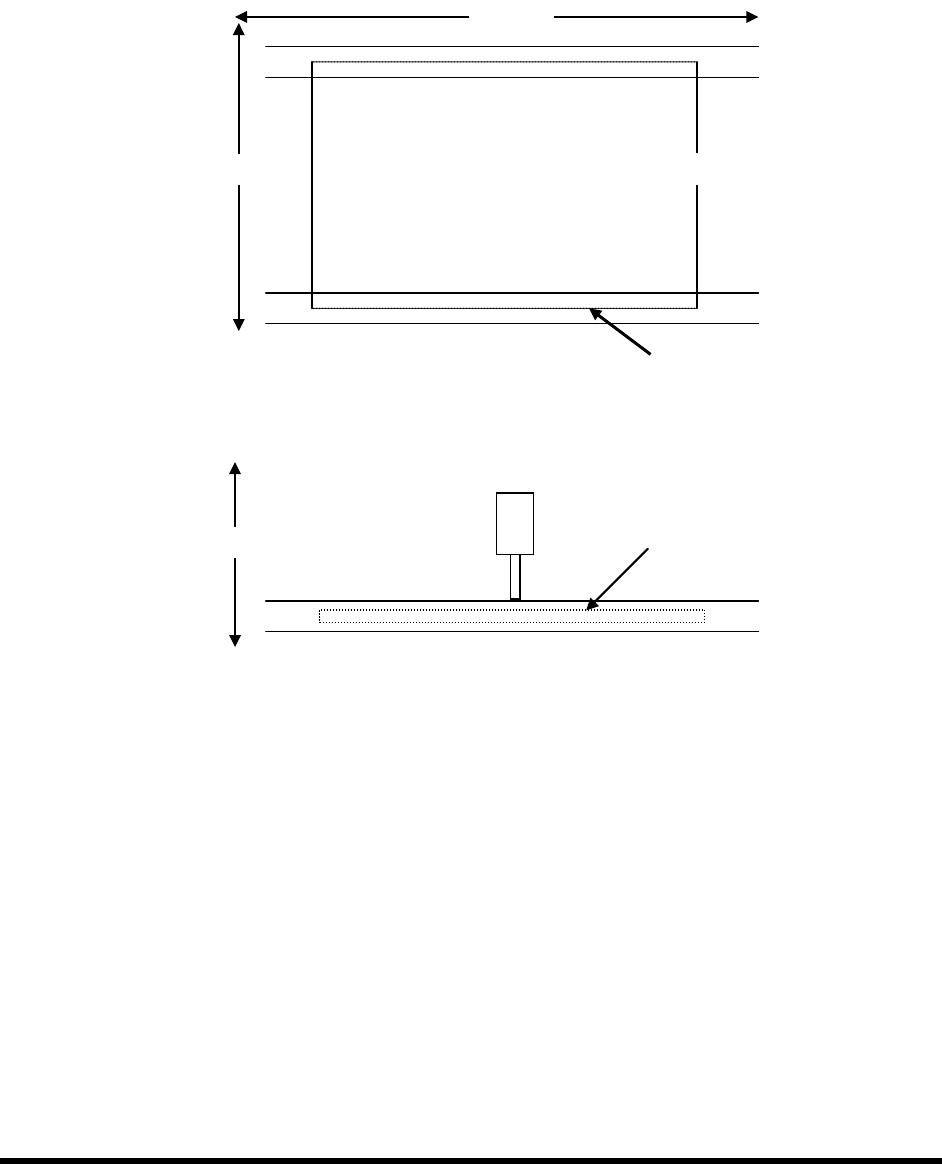
3. Teach each coordinate separately as described below. See Figure 6-12 for coordinate
locations.
NOTE The coating applicator must be installed on the robot to teach the X and Y-
coordinates.
a. To teach the X-coordinate, move the coating applicator until the point is directly over
the leading edge of the board (X-coordinate on the Top View) and click on the
Teach X button.
b. To teach the Y-coordinate, move the coating applicator until the point is directly over
the front edge of the board (Y-coordinate on the Top View) and click on the
Teach Y
button.
6-12 Configuration and Characterization
4. Install the nozzle used to configure the tool on the coating applicator to teach the
Z-coordinate. See Figure 6-12 for coordinate location.
a. To teach the Z-coordinate, carefully lower the nozzle until it is just touching the
surface of the board (Z-coordinate on the Side View) .
b. Click on the
Teach Z button.
Figure 6-12 Teaching XYZ Coordinates
X-Axis
Y-Axis
Z
Side View
Y
Top View
X
Z-Axis
Configuration and Characterization 6-13
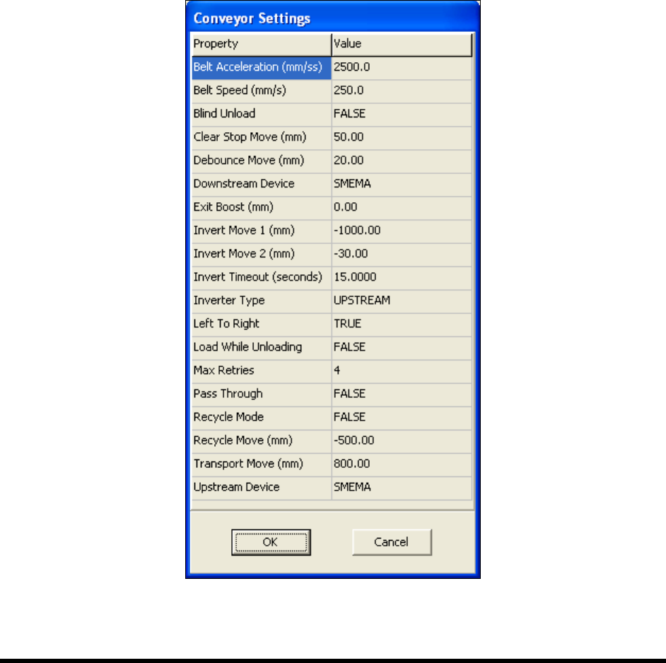
6.10 Conveyor Configuration
To configure the conveyor:
1. Click on
Configure > Conveyor Settings from the ECXP Edit Screen.
The Conveyor Settings dialog box shown in Figure 6-13 opens.
NOTE The Conveyor Settings dialog box also contains Inverter configuration settings. See
6.11 Inverter Configuration.
2. Enter the desired property values.
See Table 6-1 for a description and default value for each property.
3. Click
OK when done.
Figure 6-13 Conveyor Settings Dialog Box