SL940-Install-Ops-Maintenance-7210918_B.pdf - 第116页
6-8 Configura ti on and C hara cterizat ion 6.7 Tool Configur ati on A tool cons ist s of a coating applicator and nozz le . The Tool Config uration dialog box allows you t o set the offset for ea ch tool and perform a c…
Configuration and Characterization 6-7
d. Click on the Fault Color field and select a color.
This is the color of the Fault Message displayed on the Fault Monitor.
e. Click on the
Trigger Message field and select a trigger for the fault from the dropdown
menu, or type in any other message that goes into the fault log.
f. Click on the
Clear Message field and select the event that clears the message from the
dropdown menu, or type in any other message that goes into the fault log.
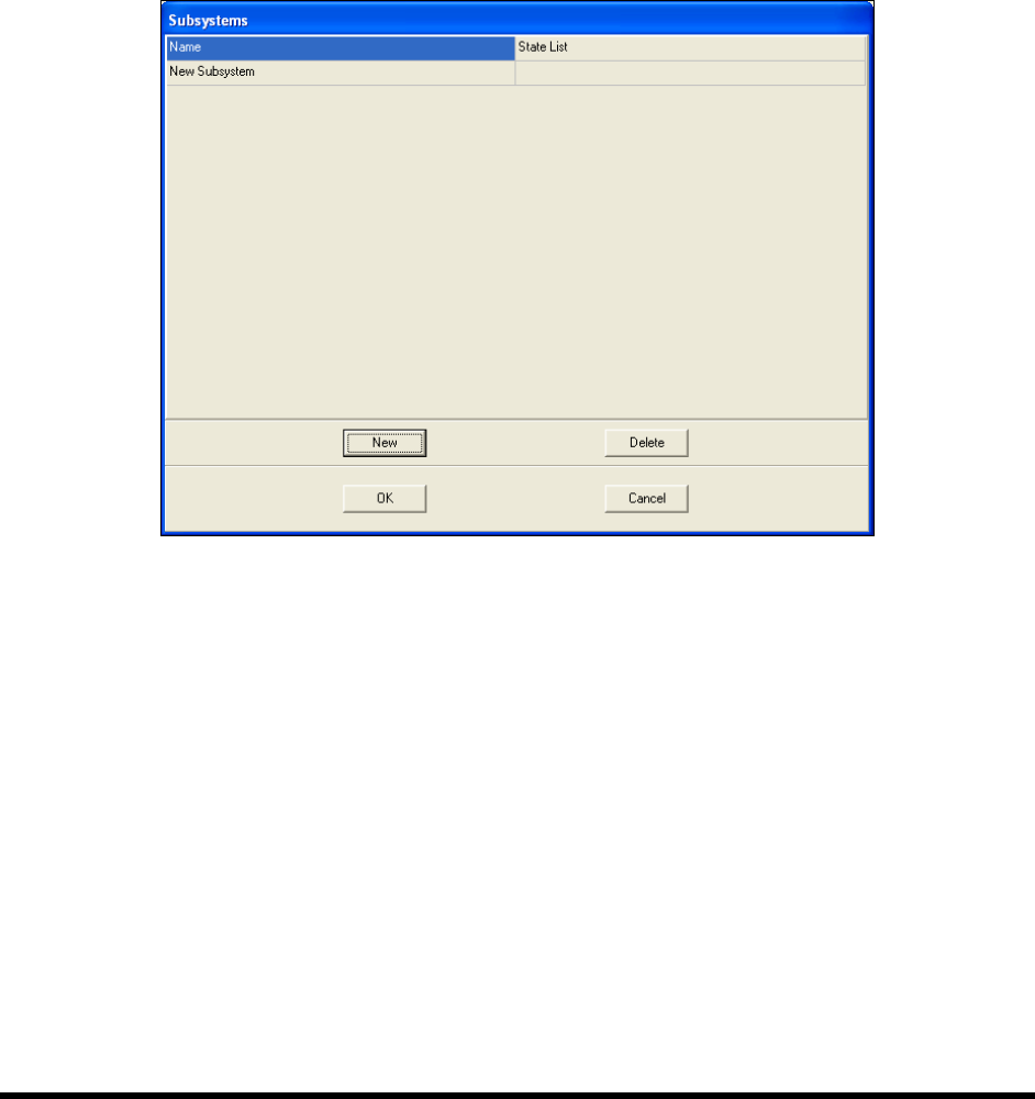
4. Create a Subsystem.
a. Click on
Configure > Status Monitoring > Beacon Configuration > Subsystems.
b. Click on
New.
Figure 6-7 Subsystem Dialog Box
c. Click on the Name field and type in a name for the subsystem.
d. Click on the
State List field, then the More button in the field.
The State List dialog opens.
e. Click on
New twice to create two states.
f. Click in the
Name field and give each state a name, such as On or Off, or Open or Closed.
g. Click in the
Trigger fields and select an input from the dropdown menu or type in a log
message.
6-8 Configuration and Characterization
6.7 Tool Configuration
A tool consists of a coating applicator and nozzle. The Tool Configuration dialog box allows you to set
the offset for each tool and perform a characterization.
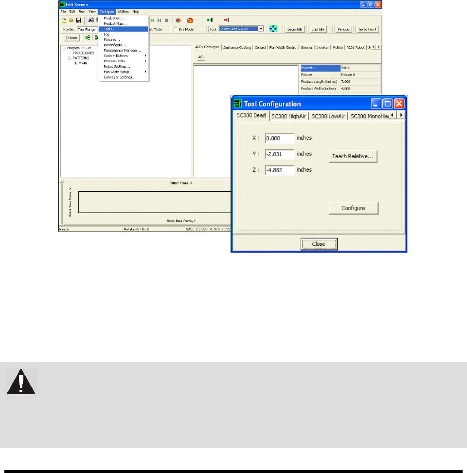
6.7.1 Tool Offset
Tool Offset is the X, Y, and Z distance from the lower tooling pin on the Z slide (also called the tool
flange, or tool arm) to the tool tip (end of nozzle). The offset for each tool must be entered into ECXP so
that the robot can position the tool tip accurately when running product programs.
To define Tool Offsets:
1. Click on
Configure > Tools from the Edit Screen menu bar (Figure 6-8).
The Tool Configuration dialog box opens.
Figure 6-8 Tool Configuration Dialog Box
2. Select the desired tool tab.
3. Enter the appropriate tool offsets for the X, Y, and Z fields.
Since the tool tip is in front of and below the tooling pin, the Y and Z offsets are always
negative. Positive X is to the right of the tooling pin.
WARNING! If Tool Offsets have already been defined and set up in the Tool Library,
correct offsets are displayed in the Tool Configuration dialog box. DO NOT
change them without assistance from your Asymtek representative. Your
Asymtek application engineer can supply you with the offset coordinates for
each tool used.
Configuration and Characterization 6-9
6.8 Fan Width Configuration
If your system is equipped with the optional Laser Fan Width Control feature, you will need to perform a
Fan Width Setup. Fan Width Control is available only for the Select Coat Tool. For more information,
contact your Asymtek representative.
To perform a fan width setup:
NOTE Before performing a fan with setup, you must perform a tool configuration and
characterization. Refer to 6.7 Tool Configuration and 6.14 Characterization for detailed
instructions.
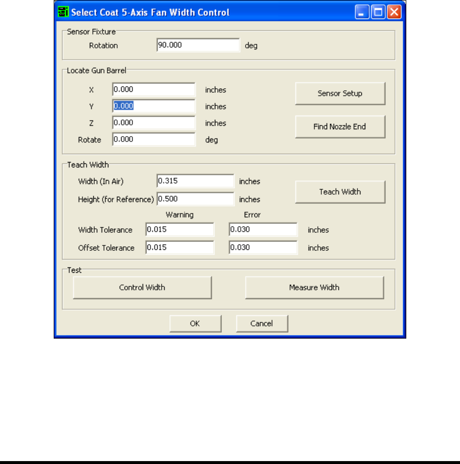
1. Select
Configure > Fan Width Setup from the ECXP Edit Screen.
The Fan Width Control Dialog Box (Figure 6-9) opens.
Figure 6-9 ECXP Fan Width Setup Dialog Box
2. Enter the appropriate information and click OK. Refer to the ECXP User Guide, LFWC
Owner's Manual, or Online Help for assistance.
NOTE As part of the Fan Width Setup procedure, you will need to perform a FWC Sensor
Setup. For additional information, refer to the manual for your Laser Fan Width Control
System or contact your Asymtek representative.