SL940-Install-Ops-Maintenance-7210918_B.pdf - 第145页
Troubleshoot ing 8-1 8 T roubleshooti ng 8.1 O ver vi ew If you hav e difficulty operating the Se lect Coat SL -940E/SL-941E Series Confo rmal Coa ting System , use this section to iden tify a possible solut ion to the p…
7-14 Maintenance
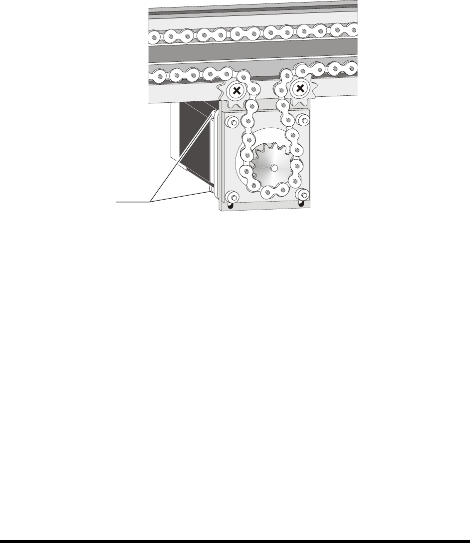
7.12 Tensioning the Conveyor Chains
To tension the conveyor chains:
1. Loosen the four mounting screws on the back of the motor bracket (Figure 7-12).
2. Let the weight of the motor set the tension in the chain.
3. Tighten the four mounting screws.
Figure 7-12 Tensioning the Conveyor Chains
Motor Bracket
Screws

Troubleshooting 8-1
8 Troubleshooting
8.1 Overview
If you have difficulty operating the Select Coat SL-940E/SL-941E Series Conformal Coating System, use
this section to identify a possible solution to the problem. If you have difficulties not listed in this section,
or the suggested solution does not correct the problem, contact Asymtek Technical Support. This section
covers the following troubleshooting procedures:
• System Power
• Pneumatics
• Conveyor
• Vision System
NOTE There are no user serviceable parts inside the electrical modules.
Refer to the ECXP User Guide or Online Help for assistance with ECXP.
8.2 Safety First
Operation of the SL-940E/SL-941E involves heat, air pressure, electrical power, mechanical devices, and
the use of hazardous materials. It is essential that every person servicing or operating the coating system
fully understands all hazards, risks, and safety precautions. Refer to Section 2 - Safety for additional
information.
WARNING! CAUTION!
To ensure optimal performance and safety, it is necessary to install the coating
system and its components in a facility that meets the necessary requirements
listed in Section 10 - Specifications. If you have any questions, please contact
Asymtek Technical Support.
8.3 Record Keeping
The type of procedure performed should be recorded in maintenance records for the coating system.
Dates, part numbers/serial numbers of replaced parts, names of technicians, and other pertinent data
should be recorded.
WARNING! Allow only qualified personnel to perform system troubleshooting. Observe and
follow the safety instructions in this document and all other related
documentation. Failure to do so may cause serious bodily injury to the user or
damage to the equipment.
8-2 Troubleshooting
8.4 Basic System Troubleshooting
8.4.1 System Power
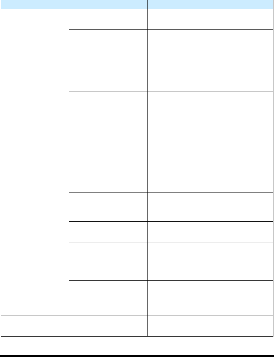
Table 8-1 System Power Troubleshooting
Symptom Possible Cause Recovery
No power to major system
components
The ON (l) button has not been
pressed
Press ON (l) on the front panel. The green button
will flash for 60 seconds and then the machine will
turn on.
Main power cable
disconnected
Connect the main power cable to an AC power
source.
Main power circuit breaker
turned OFF
Turn ON the main power circuit breaker at the rear
of the system.
A circuit breaker has been
tripped.
The SL-940E/SL-941E incorporates circuit
breakers with a “push to reset” feature rather than
fuses. For detailed troubleshooting of power
related issues, consult the power manager block
diagram or call Asymtek Technical Support.
EMO button has been
activated
1. Turn the EMO button clockwise until it
pops out. The EMO buttons at the front and
rear of the system interrupt power to all power
connections except
the laptop computer.
2. Press ON (l) on the front panel.
Interlock circuit is interrupted
Make sure the hood is closed. The interlock places
the servo control system in a low power state that
is just sufficient to hold the positioner in place for
syringe changes. Opening the front hood does not
completely power down the SL-940E/SL-941E, and
does not power off the PC.
Spill pan not in place
The spill pan must be in place for proper
ventilation. A spill pan interlock sensor detects
proper installation. If the spill pan is not in place,
the system will not operate.
Machine Exhaust Ventilation
not ON
Make sure exhaust vent duct is connected to the
factory exhaust system ductwork according to
specifications.
(600 scfm air at 1 in. water column static pressure)
Power control cable
disconnected
Verify the power control cables are properly routed
and connected from the Power Manager to the
front panel switches.
Button failure Call a trained service technician.
Applicator does not
operate.
Loose fluid, or electrical
connections; restricted hoses
Call a trained service technician.
Micro-adjust knob is fully
closed
Open micro-adjustment to characterized setup
value (value between 1 and 12 marks of turn).
Applicator ON/OFF switch is
OFF
Turn Applicator ON/OFF switch to the ON position.
Air to applicator is
disconnected or connected to
the wrong quick disconnect
Reconnect air line from applicator to quick
disconnect on Z-head.
Safety Interlock fails to
reset.
Interlock Activated
Make sure the hood is closed and the spill pan is in
place. If the interlock still fails to reset, call a
trained service technician.