SL940-Install-Ops-Maintenance-7210918_B.pdf - 第129页
Configuration a nd C haract erizati on 6- 21 NOTE Refer to the cha racteriz ation shee t ( Figur e 6-19 ) fo r Steps 10 to 12. 10. Posi tion the too l tip or ca mera over the left inter sectio n of the dotted lines a…
6-20 Configuration and Characterization
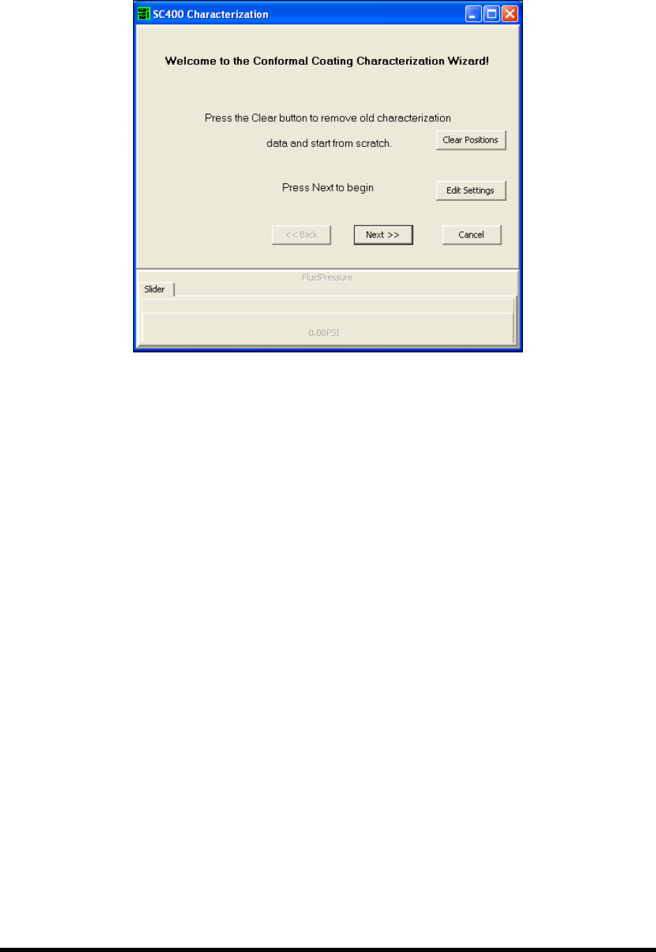
Figure 6-18 ECXP Characterization Wizard Dialog Box
3. Click Clear Positions and then click OK to confirm.
If you have performed a characterization before, the old test area coordinates are used
unless you clear them.
4. Click
Next.
5. Click
Yes when prompted to teach the substrate height.
6. Teach the substrate height.
a. Place a characterization sheet (Figure 6-19) in the workcell.
b. Lower the tool tip to the substrate and click
Teach Z
c. Click
OK
7. Enter the dispense height.
The following variables should be considered:
- Height of tallest component to be coated
- Width of coating stripe
- Coating material flow rate and viscosity
- Coating stripe overlap
8. Enter the desired rotate position and click
Next (for applicators equipped with rotate and
cross-cut nozzles).
9. Enter the desired dispense speed and click
Next.
Configuration and Characterization 6-21
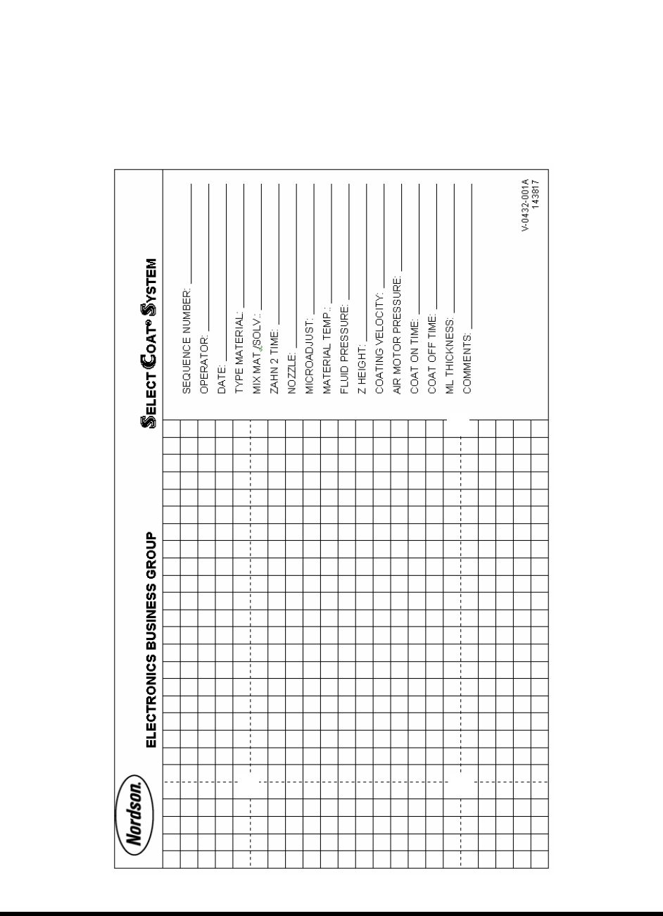
NOTE Refer to the characterization sheet (Figure 6-19) for Steps 10 to 12.
10. Position the tool tip or camera over the left intersection of the dotted lines
and click Next.
11. Position the tool tip or camera over the right intersection of the dotted lines
and click
Next.
12. Position the tool tip or camera over the right dotted line and the back line
and click Next.
Remove any teaching devices before continuing.
Figure 6-19 Characterization Sheet
6-22 Configuration and Characterization
13. Click Next.
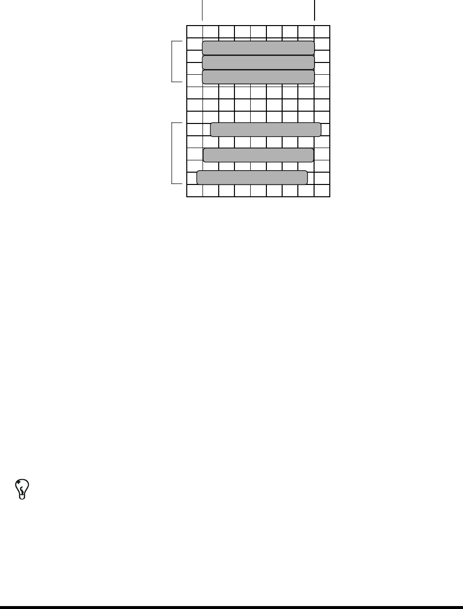
The Wizard will now apply three stripes of material to the test area (See Figure 6-20).
Desired Start Desired End
2
nd
3 passes
1
st
3 passes
Figure 6-20 Material Characterization
14. You will be prompted to teach the coordinates of the test area.
a. Teach the stripe with the best starting accuracy and click
Next.
If none are exact but one stripe starts too soon and the next too late, teach between
the two stripes. The wizard interpolates the values of the two.
b. Teach the stripe with the best ending accuracy and click
Next.
If none are exact but one stripe ends too soon and the next too late, teach between the
two stripes. The wizard interpolates the values of the two.
15. Enter the stripe width and click
Next.
The wizard applies three more stripes to the test area.
16. Check the starting and ending points of the second three stripes. If they are not accurate,
rerun the characterization, making adjustments as necessary to obtain the best results.
17. The settings will be displayed for your approval.
TIP To perform a characterization from the ECXP Operator screen, click on Configure >
Tool > Toolname
. The Tool Configuration dialog box opens.