SL940-Install-Ops-Maintenance-7210918_B.pdf - 第130页
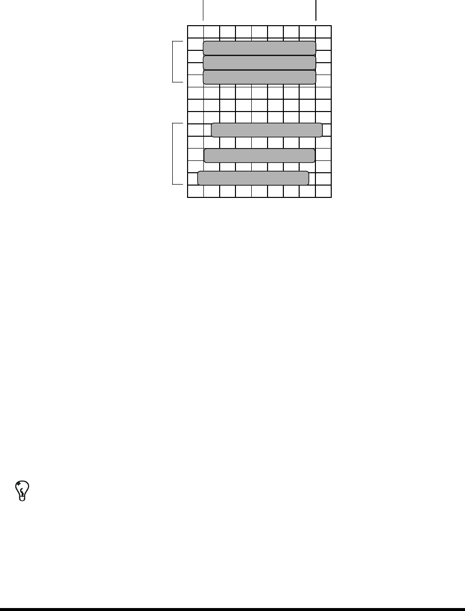
6- 22 Configuration a nd C haracte rization 13. Click Next . The W iza rd wi ll now app ly thr ee str ipe s of m ate rial to the te st a rea (See Figur e 6- 20 ). Desired Start Desired End 2 nd 3 passes 1 st 3 passes F…
Configuration and Characterization 6-21
NOTE Refer to the characterization sheet (Figure 6-19) for Steps 10 to 12.
10. Position the tool tip or camera over the left intersection of the dotted lines
and click Next.
11. Position the tool tip or camera over the right intersection of the dotted lines
and click
Next.
12. Position the tool tip or camera over the right dotted line and the back line
and click Next.
Remove any teaching devices before continuing.
Figure 6-19 Characterization Sheet
6-22 Configuration and Characterization
13. Click Next.
The Wizard will now apply three stripes of material to the test area (See Figure 6-20).
Desired Start Desired End
2
nd
3 passes
1
st
3 passes
Figure 6-20 Material Characterization
14. You will be prompted to teach the coordinates of the test area.
a. Teach the stripe with the best starting accuracy and click
Next.
If none are exact but one stripe starts too soon and the next too late, teach between
the two stripes. The wizard interpolates the values of the two.
b. Teach the stripe with the best ending accuracy and click
Next.
If none are exact but one stripe ends too soon and the next too late, teach between the
two stripes. The wizard interpolates the values of the two.
15. Enter the stripe width and click
Next.
The wizard applies three more stripes to the test area.
16. Check the starting and ending points of the second three stripes. If they are not accurate,
rerun the characterization, making adjustments as necessary to obtain the best results.
17. The settings will be displayed for your approval.
TIP To perform a characterization from the ECXP Operator screen, click on Configure >
Tool > Toolname
. The Tool Configuration dialog box opens.
Maintenance 7-1
7 Maintenance
7.1 Overview
Performing the recommended maintenance procedures on the Select Coat SL-940E/SL-941E Series
Conformal Coating System at the intervals suggested in this section increases system life and ensures
high quality dispensing performance for every production run. This section covers the following topics:
•
Hazardous Materials
•
Cleaning the Fluid Filter
•
Record Keeping
•
Lubricating the Cables and Linear Guides
•
Routine Maintenance Procedures •
Tensioning the Cables
•
Cleaning the Spill Pan
•
Tensioning the Conveyor Chains
•
Emptying the Water Trap
7.2 Safety First
Operation of the SL-940E/SL-941E involves heat, air pressure, electrical power, mechanical devices, and
the use of hazardous materials. It is essential that every person servicing or operating the coating system
fully understands all hazards, risks, and safety precautions. Refer to Section 2 - Safety for additional
information.
WARNING! CAUTION!
To ensure optimal performance and safety, it is necessary to install the coating
system in a facility that meets the necessary requirements listed in Section 10 -
Specifications. If you have any questions, please contact Asymtek Technical
Support.
7.3 Hazardous Materials
Some maintenance procedures involve the use of hazardous materials. Always follow all applicable
national and local statutes and regulations, facility safety practice, and the material manufacturer's MSDS
recommendations.
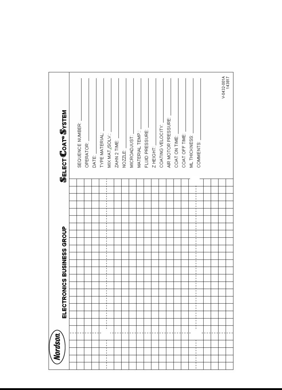
7.4 Record Keeping
The type of maintenance performed (such as preventive and parts replacement) should be recorded in
maintenance records for the coating system. Dates, part numbers/serial numbers of replaced parts, names
of technicians, and other pertinent data should be recorded.
WARNING! Allow only qualified personnel to perform the following tasks. Observe and follow
the safety instructions in this document and all other related documentation.