SL940-Install-Ops-Maintenance-7210918_B.pdf - 第67页
Pow er - up an d Test in g 4-7 4.9 Starting Eas y Coat for Window s ( ECXP) To sta rt/e xit ECXP : 1. Double click the E CX P icon on the Windows desktop. As an alternative, y ou may click on the Windows Start menu and…
4-6 Power-up and Testing
4.8 Camera States
An optional Dalsa-Coreco Genie M640 digital 640 x 480 pixel camera communicates bi-directionally to
the laptop computer via Gigabit Ethernet. After the Genie software package installation, the GigE Server
icon is visible in the desktop taskbar tray area. The icons and descriptions are shown in Table 4-1.
Table 4-1 Genie Camera States
Icon State Description
Device Available
The GigE server tray icon when the Genie device is found. It will
take a few seconds for the GigE Server to refresh its state after the
Genie has obtained an IP address.
Device IP Error
The GigE server tray icon shows a warning when a device is
connected but there is some type of IP error.
Device Not
Available
A red X will remain over the GigE server tray icon when the Genie
device is not found. This indicates a major network issue.
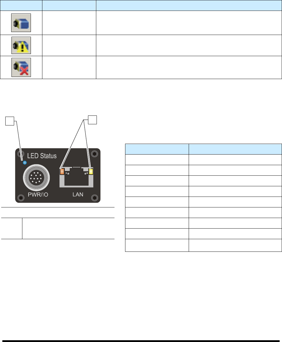
The Genie has one multicolor LED to provide a simple visible indication of camera state. Additionally the
RJ45 has two LEDs for network status conditions (Figure 4-3). LED Status indicators are described in
Table 4-2.
Table 4-2 Camera Status Indicators
LED Status Description
LED's are OFF No Power to Camera
Steady Red Camera Not Initialized
Slow Flashing Red Camera Initialization Problem
Fast Flashing Red Camera Overheating
Steady Blue IP Address Assigned
Item Description
Slow Flashing Blue Waiting for an IP Address
1 Camera Status LED Fast Flashing Blue Ethernet Cable Disconnected
2 Network Status LED Steady Green Application Linked to the Camera
Figure 4-3 Camera LED's (Rear View)
Slow Flashing Green Trigger Acquisition in Progress
1
2
Power-up and Testing 4-7
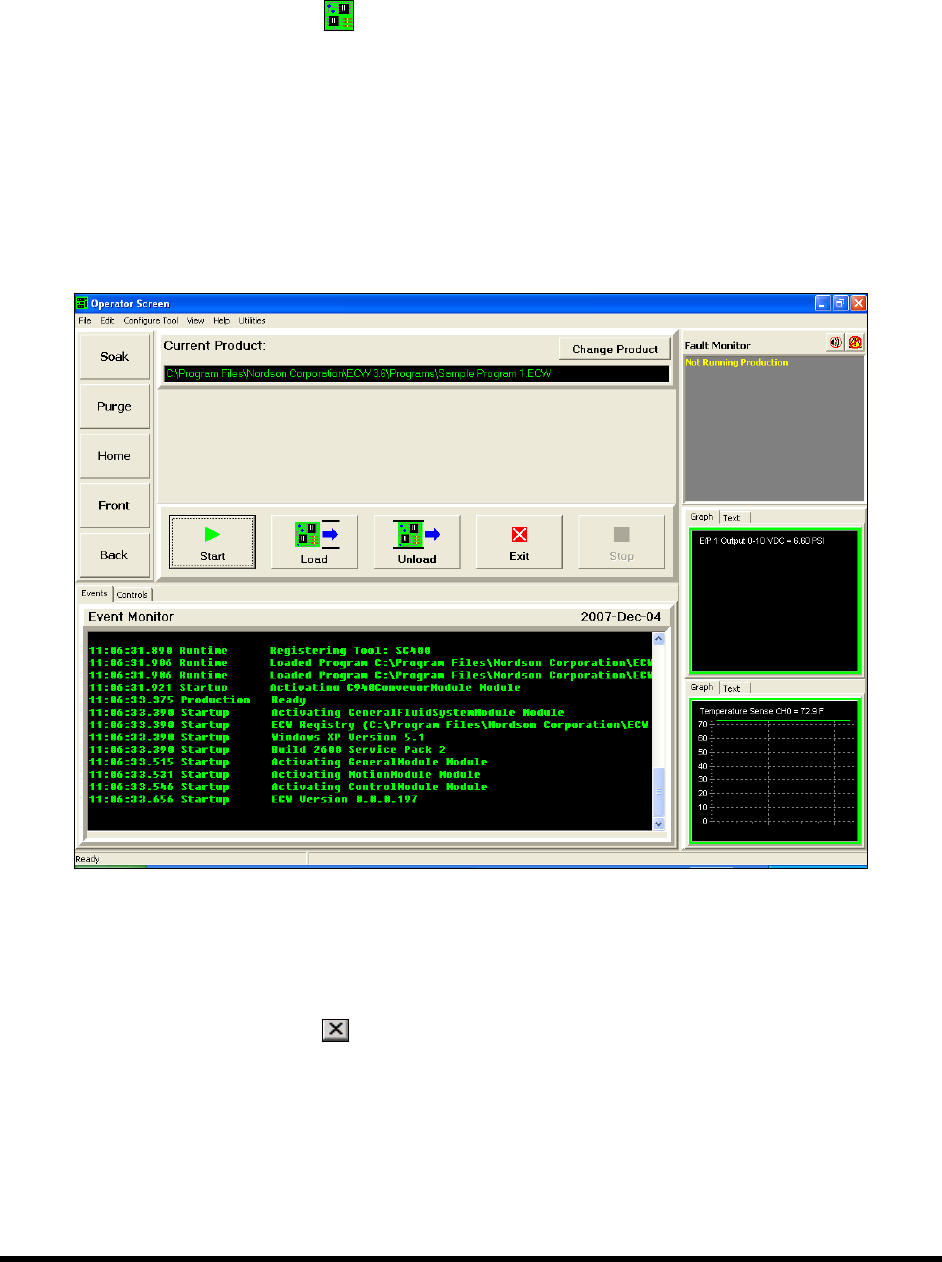
4.9 Starting Easy Coat for Windows (ECXP)
To start/exit ECXP:
1. Double click the ECXP
icon on the Windows desktop.
As an alternative, you may click on the Windows
Start menu and select
Programs > ECXP to start the ECXP software.
The Dispenser will find Home in the Z-Axis, X-Axis, and Y-Axis, respectively.
The ECXP Operator Screen shown in Figure 4-4 will open.
NOTE The Operator Screen will vary slightly depending on system configuration.
Figure 4-4 Starting ECXP
NOTE If ECXP does not start, or you receive error messages during start-up, please contact
Asymtek Technical Support.
2. To exit ECXP, click on
or select File > Exit from the Operator Screen menu bar.
NOTE Refer to Section 5 - Operation for instructions on loading and running ECXP programs.
4-8 Power-up and Testing
4.10 Testing the System
After initial installation and power-up, the system must be tested to ensure that it is working properly.
This section includes the procedures for testing the following:
Robot/Conveyor I/O Conveyor Function
Pneumatics Coating System Options
Robot (Dispensing Head) Function
These procedures should be performed on initial installation and after the machine has been moved
or serviced.
CAUTION! The following procedures should only be performed by a trained service technician.
4.11 Robot/Conveyor I/O
To test the Robot I/O:
1. Follow the instructions in 4.9 Starting Easy Coat for Windows (ECXP) to start ECXP.
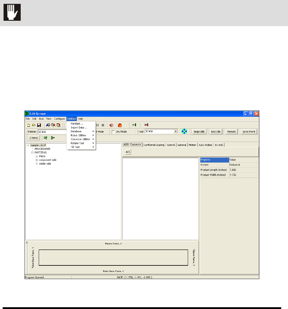
2. Select
Edit > Edit Mode from the ECXP Operator Screen menu bar to access the ECXP
Edit Screen.
3. Select
Utilities from the Edit Screen menu bar (Figure 4-5).
Figure 4-5 ECXP Edit Screen - Utilities Menu