SL940-Install-Ops-Maintenance-7210918_B.pdf - 第59页
Insta llat ion 3-9 3.7 Installi ng the La ptop Computer NOTE The laptop com puter is shipped f rom the factory fully charged 1. Rem ove the lapto p comput er f rom i t s pa cka ging . 2. Rem ove the key s from the lock…
3-8 Installation
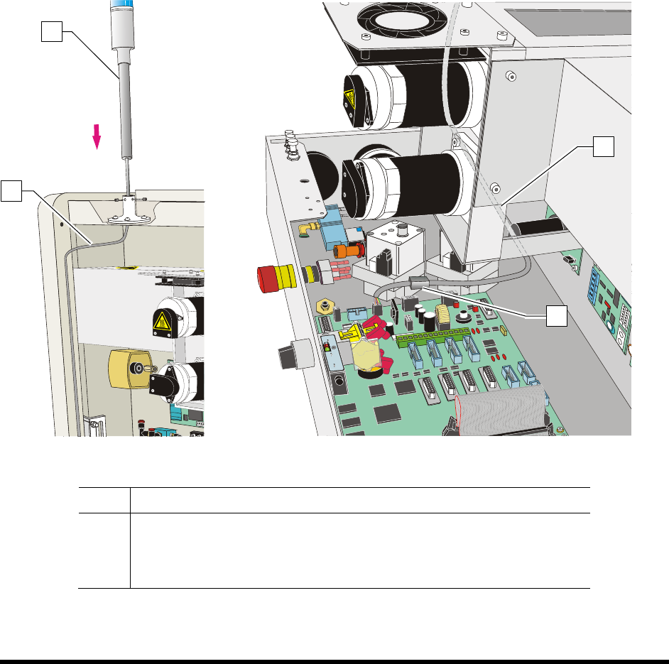
3.6 Installing the Light Beacon
1. Loosen the five (5) screws on the electronics/pneumatics cover and remove it.
2. Remove the ferrite bead from the cable.
3. Feed the electrical cable on the light beacon through the top of the light beacon base
(Figure 3-8A).
4. Set the light beacon into the base and tighten the set screws.
5. Route the electrical cable as shown in Figure 3-8A and Figure 3-8B.
6. Make the beacon electrical connections (Figure 3-8B).
7. Replace the ferrite bead.
8. Replace the electronics/pneumatics cover and tighten the screws that hold the panels in place.
Figure 3-8A
Figure 3-8B
Item Description
1 Beacon
2 Electrical Cable
3 Ferrite Bead
Figure 3-8 Installing the Light Beacon
1
2
2
3
Installation 3-9
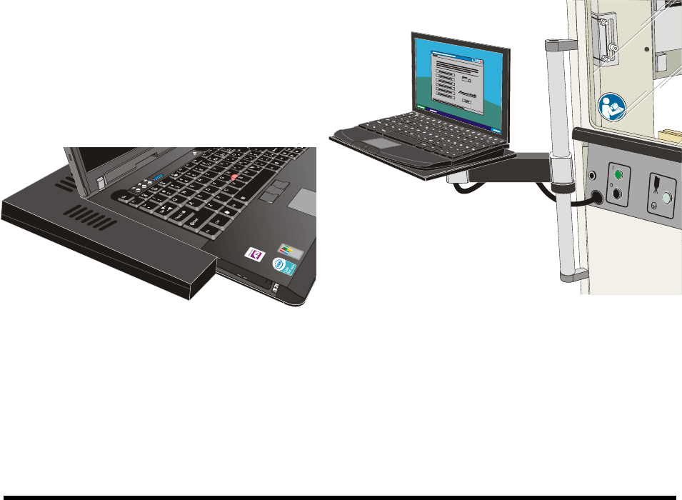
3.7 Installing the Laptop Computer
NOTE The laptop computer is shipped from the factory fully charged
1. Remove the laptop computer from its packaging.
2. Remove the keys from the lock and give them to the person responsible for the machine.
The keys are used to lock the laptop computer to the dispensing system tray.
3. Move the laptop tray arm bracket on the dispensing system so that the laptop tray is facing
forward.
4. Attach the USB and Network cables and grounding wire attachment to their respective ports
on the computer.
5. Attach the power cable to the rear of the computer.
NOTE The laptop is adhered to the tray with a hook and loop fastener. Align the laptop
computer before placing it on the tray.
6. With the laptop lid closed, align the computer with the covers such that no gaps exist on the
left hand side or the back edge.
7. Gently press the laptop onto the base.
8. Attach the locking cable to the laptop.
Figure 3-9 Aligning the Computer to the Tray Figure 3-10 Laptop Computer Installed
3-10 Installation
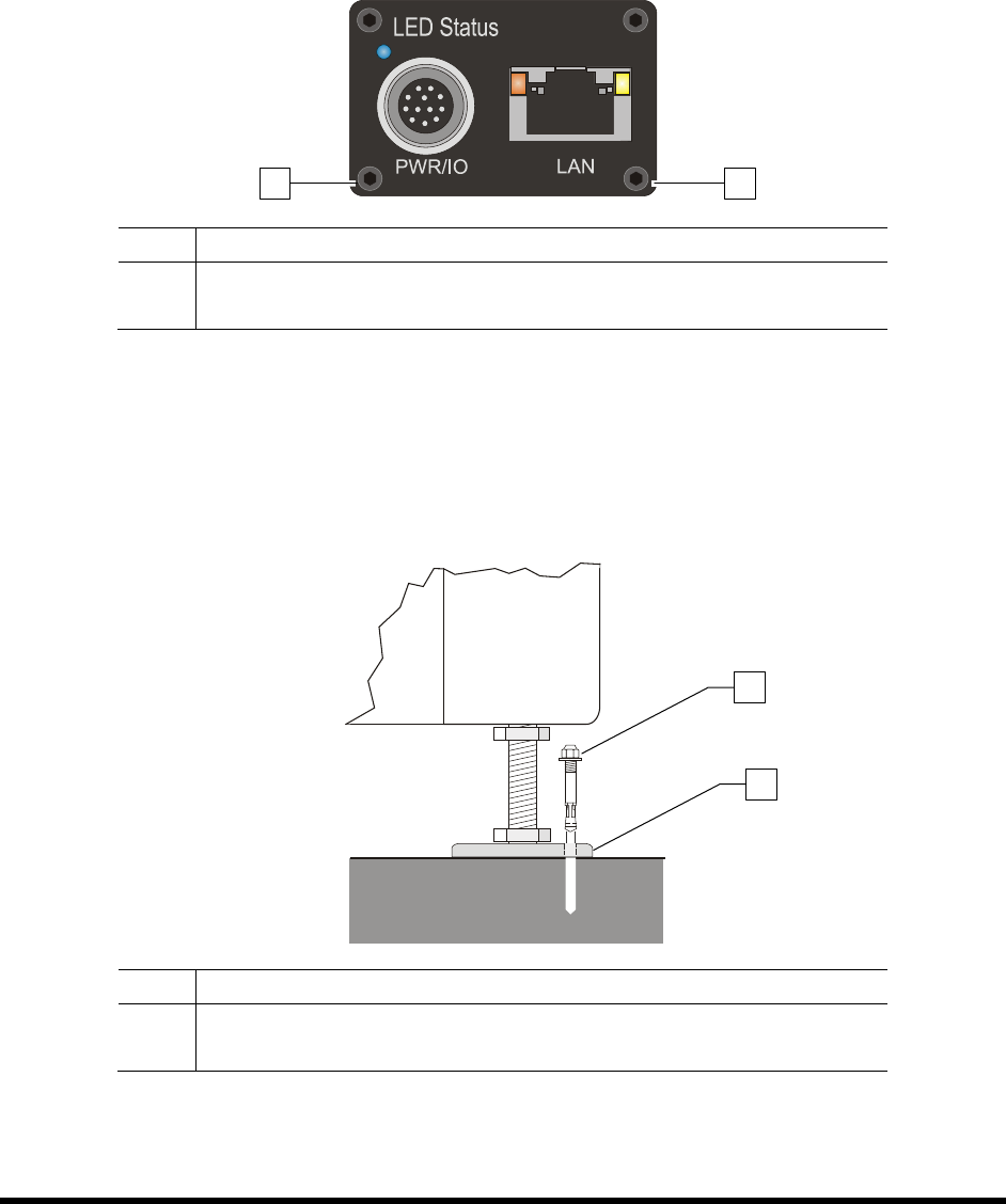
3.8 Installing the Optional Genie Camera
NOTE The Genie Framework Software is installed at the factory prior to shipping.
To connect the camera:
1. Connect a power supply to the Genie camera (Figure 3-11).
2. Connect an RJ5 Ethernet cable from the camera to the laptop computer.
Item Description
1 Power Connection
2 Ethernet Connection
Figure 3-11 Camera (Rear View)
3.9 Anchoring the Coating System
To prevent movement that could cause injury to personnel and damage to the coating system and facility,
each coating system leveler (foot) should be anchored to the floor with one wedge anchor (Figure 3-12).
Refer to Facility Specification SL94XE (P/N 7218847).
Item Description
1 Wedge Anchor
2 Leveler
Figure 3-12 Anchoring the Coating System
NOTE You may also use the shipping brackets to anchor the coating system.
1
2
2
1