SL940-Install-Ops-Maintenance-7210918_B.pdf - 第26页
1- 12 Introduction 1.12.1.1 Front Panel Below a re descrip tions of SL -940E/SL-941E front panel buttons as shown in Figur e 1-4. NOTE Refer to Secti on 5 - Oper at ion for de taile d de scr ipt ion s of a ll fr ont pa…
Introduction 1-11
Figure 1-3B SL-941E Front View (Tooling Rails shown)
Item Name Description
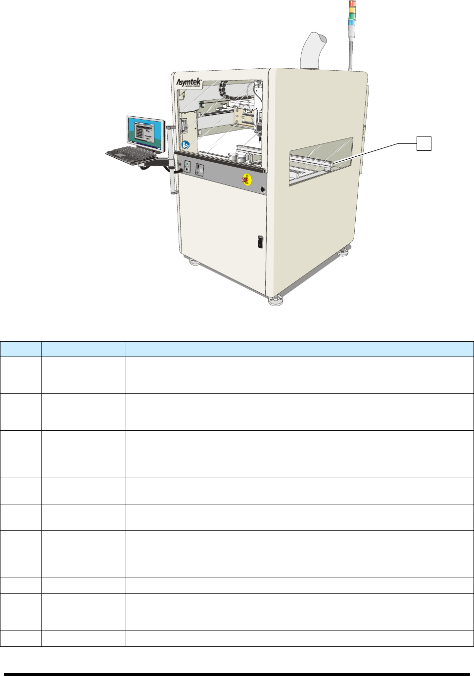
1 Front Hood
The Front Hood allows the operator to view and access the dispensing area. A
sensor connects the hood to the Safety Interlock System. If the hood is opened
when a program is running, all dispensing motion stops.
2 Laptop Computer
The coating system features a laptop computer, mounted on an adjustable
height bracket. The laptop computer runs the Easy Coat for Windows XP (ECXP)
coating software.
3 Front Panel
The Front Panel contains the system ON and OFF buttons, the Emergency
Machine Off (EMO) button, the Grounding Strap connection, and the Applicator
On/Off button. Refer to Section 5 - Operation for detailed descriptions of front
panel functions. See Figure 1-4.
4 Coating Area
The Robot, Solvent Cups, Conveyor, Stop Pins, and Board Sensors are all
located in the coating area. See Figure 1-5.
5 Front Cabinet
The Front Cabinet houses the Spill Pan, Laser Fan Width Control Amplifier
(optional), and the Reservoir Air Pressure Regulator. See Figure 1-7.
6
Levelers
(Foot Pads)
The Levelers are the footpads of the coating system. The levelers are adjusted
during installation and should not need attention unless the system is moved to a
new location. To protect the coating system from moving during an earthquake,
the levelers can be anchored to the floor. See 2.8 Earthquake Precautions.
7 Conveyor See 1.12.1.3 Conveyor.
8 Light Beacon
The Light Beacon signals the operator of system status by displaying a colored
solid or blinking light and/or issuing an audible tone. Refer to Section 2 - Safety
for additional information.
9 Tooling Rails See 1.12.1.2 Dispensing Area.
Figure 1-3 Front View
9
1-12 Introduction
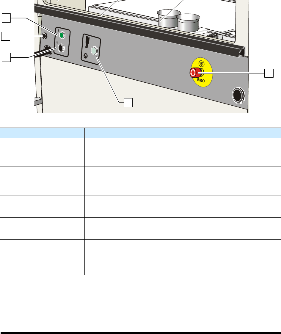
1.12.1.1 Front Panel
Below are descriptions of SL-940E/SL-941E front panel buttons as shown in Figure 1-4.
NOTE Refer to Section 5 - Operation for detailed descriptions of all front panel buttons and
functions.
Item Name Description
1 Start Button
The Start button is a push button located on the front panel. It turns on the
power to the coating system. The Start button glows green when pushed,
and continues to glow until the Stop button or Emergency Machine Off
(EMO) button is pressed.
2
Grounding Strap
Connector
Grounding straps worn by the operator or technician attach to this
connector. This prevents electrostatic discharge (ESD) damage to
workpieces and conformal coating system electronics during coating
operations and servicing.
3 Stop Button
The Stop button is a push button located on the front panel. When pushed,
it stops all power to the conformal coating system, with the exception of the
laptop computer.
4 Applicator ON/OFF
Press Applicator ON/OFF to turn the coating applicator on and off. This
feature can be used to test run a program without dispensing fluid (dry
mode).
5
Emergency Machine
Off (EMO)
Activating the EMO (E-Stop) vents all pressure in the pneumatic system,
de-energizes the robot motors, and cuts power to all system components
except the laptop computer. An EMO button is located on the front and rear
of the conformal coating system. Refer to Section 2 - Safety for additional
information.
Figure 1-4 SL-940E/SL-941E Front Panel
4
2
1
3
5
Introduction 1-13
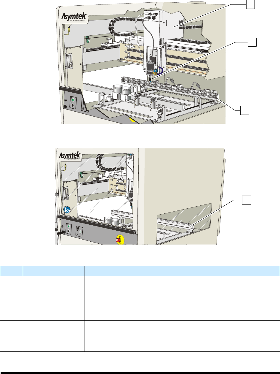
1.12.1.2 Dispensing Area
Below are functional descriptions of SL-940E/SL-941E components shown in Figure 1-5.
Figure 1-5A SL-940E Dispensing Area
Figure 1-5A SL-941E Dispensing Area
Item Name Description
1 Robot
The Robot moves in the XYZ planes. It is controlled through the coating
system software. The coating applicator, camera, laser pointer
programming tool, and board present sensor are mounted on the robot
2
Conformal Coating
Applicator
(SC-400 shown)
Depending upon your application requirements, the Select Coat SL-
940E/SL-941E Series Conformal Coating System can be configured with
any of the conformal coating applicators listed in Table 1-1.
3
Chain Conveyor
(SL-940E)
See 1.12.1.3 Conveyor.
4
Tooling Rails
(SL-941E)
The Tooling Rails are standard on the SL-941E and secure the workpiece
for batch system operations.
Figure 1-5 Dispensing Area
1
2
3
4