SL940-Install-Ops-Maintenance-7210918_B.pdf - 第135页
Maintenance 7-5 7.8 Cl eaning the Flui d Filter WARNING ! CAUTION! Follow M SDS recom m endations f or the pr oper ha ndling an d dis posal of all mater ials when c leaning t he f luid filte r . Al wa ys wear appropri at…
7-4 Maintenance
7.7 Emptying the Water Trap
Moisture from the outside air can condense in the pneumatic system. The water trap collects this
condensed moisture. You must empty it weekly or whenever it is full.
To empty the water trap:
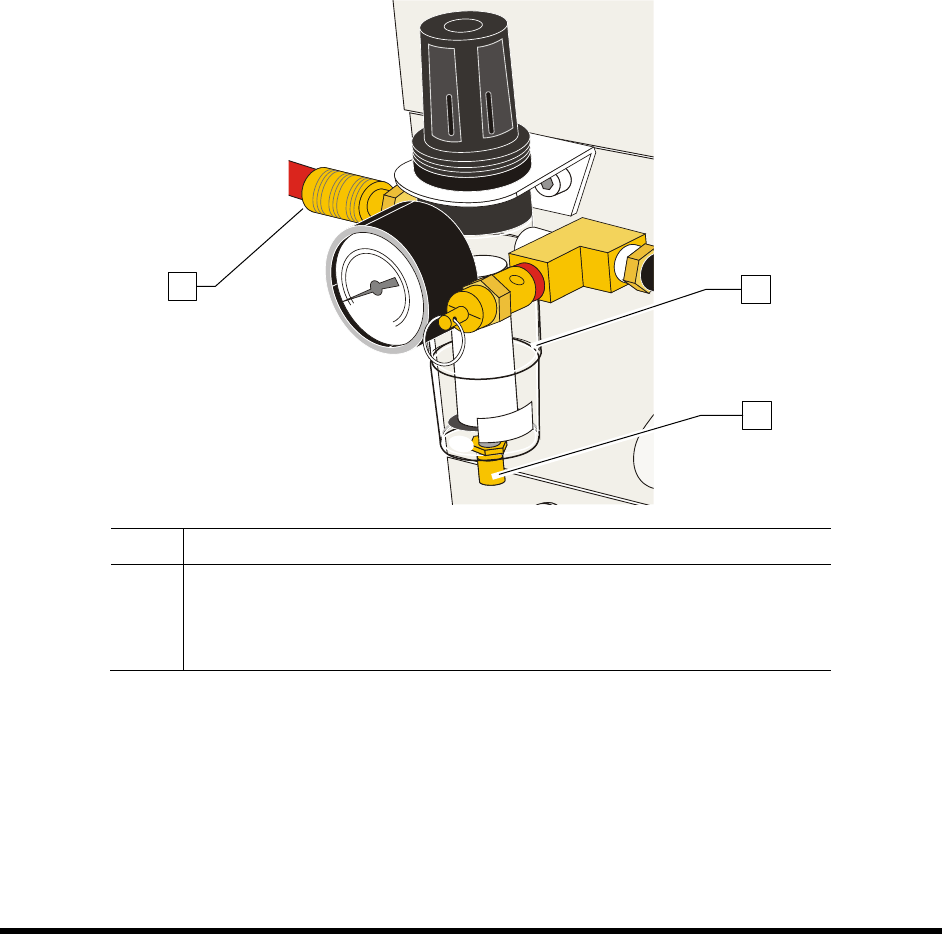
1. Locate the water trap (Figure 7-2) at the rear of the system.
2. Disconnect the facility air supply from the main air inlet.
3. Hold a container under the water trap to catch the water.
4. Using your finger, push the water drain knob at the bottom of the assembly.
5. Reconnect the facility air supply to the main air inlet.
Item Description
1 Water Trap
2 Drain Knob
3 Main Air Inlet
Figure 7-2 Water Trap
1
2
3
Maintenance 7-5
7.8 Cleaning the Fluid Filter
WARNING! CAUTION!
Follow MSDS recommendations for the proper handling and disposal of all
materials when cleaning the fluid filter. Always wear appropriate personal
protective equipment (PPE) as recommended by facility safety practices and the
material manufacturer’s MSDS. To prevent eye injury or irritation, wear safety
goggles while performing this procedure.
To clean the fluid filter:
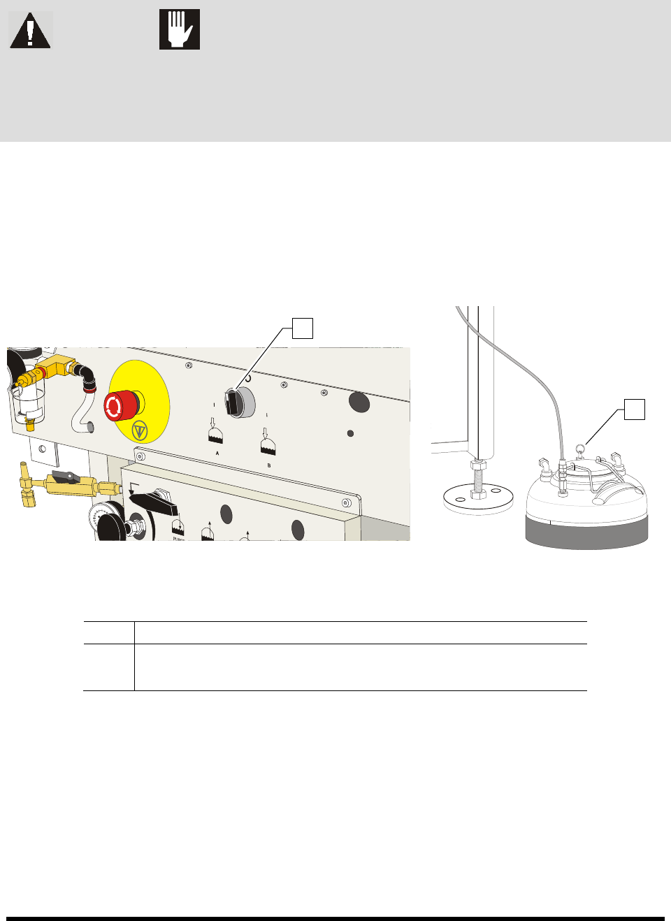
1. Turn the Reservoir Air Pressure Switch to the
OFF (0) position. See Figure 7-3.
2. Relieve residual pressure in the fluid system by opening the pressure relief valve on the fluid
reservoir.
Figure 7-3A Coating System Rear Panel Figure 7-3B Fluid Reservoir
Item Description
1 Reservoir Air Pressure Switch (right rear)
2 Fluid Reservoir Pressure Relief Valve
Figure 7-3 Relieving the Air Pressure
1
2
7-6 Maintenance
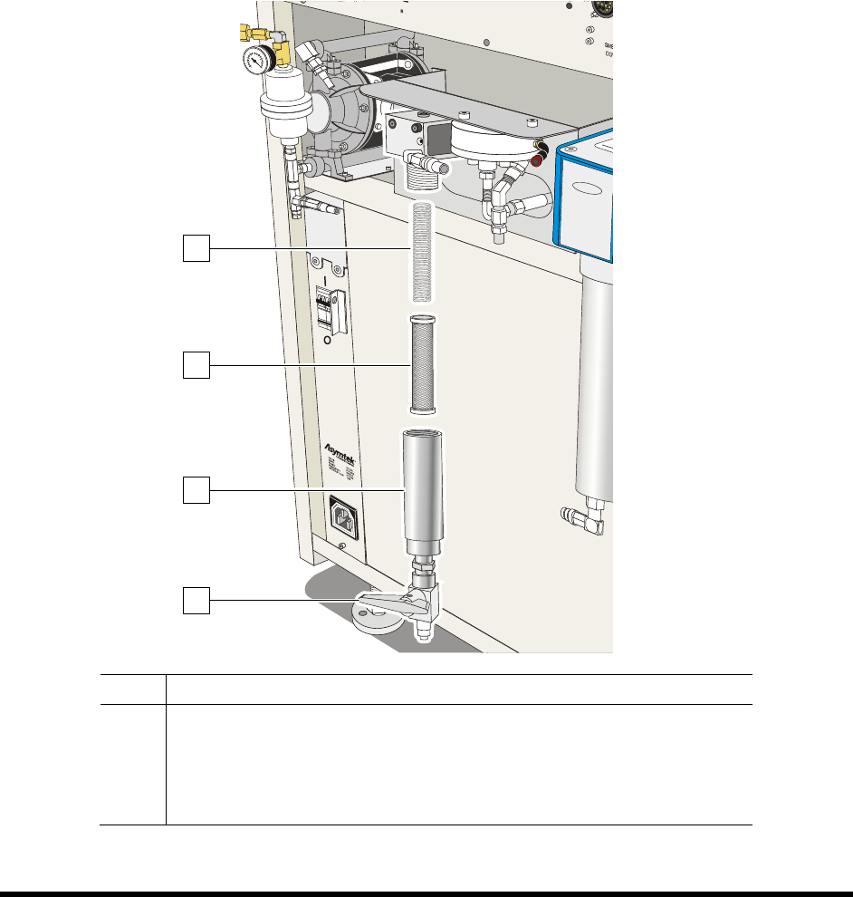
3. Drain fluid from the filter assembly by opening the ball valve.
4. Unscrew the fluid filter cap (Figure 7-4).
The fluid filter is located inside the housing.
5. Remove the filter and clean it with a proper solvent.
6. Brush the stainless steel screen with the appropriate solvent. Replace if necessary.
7. Blow filter surface with compressed air.
8. When finished, reassemble the filter and turn the Reservoir Air Pressure Switch to the
Reservoir A or Reservoir B position as applicable.
Item Description
1 Fluid Filter Spring
2 Fluid Filter
3 Housing
4 Ball Valve
Figure 7-4 Cleaning the Fluid Filter
1
4
2
3