SL940-Install-Ops-Maintenance-7210918_B.pdf - 第30页
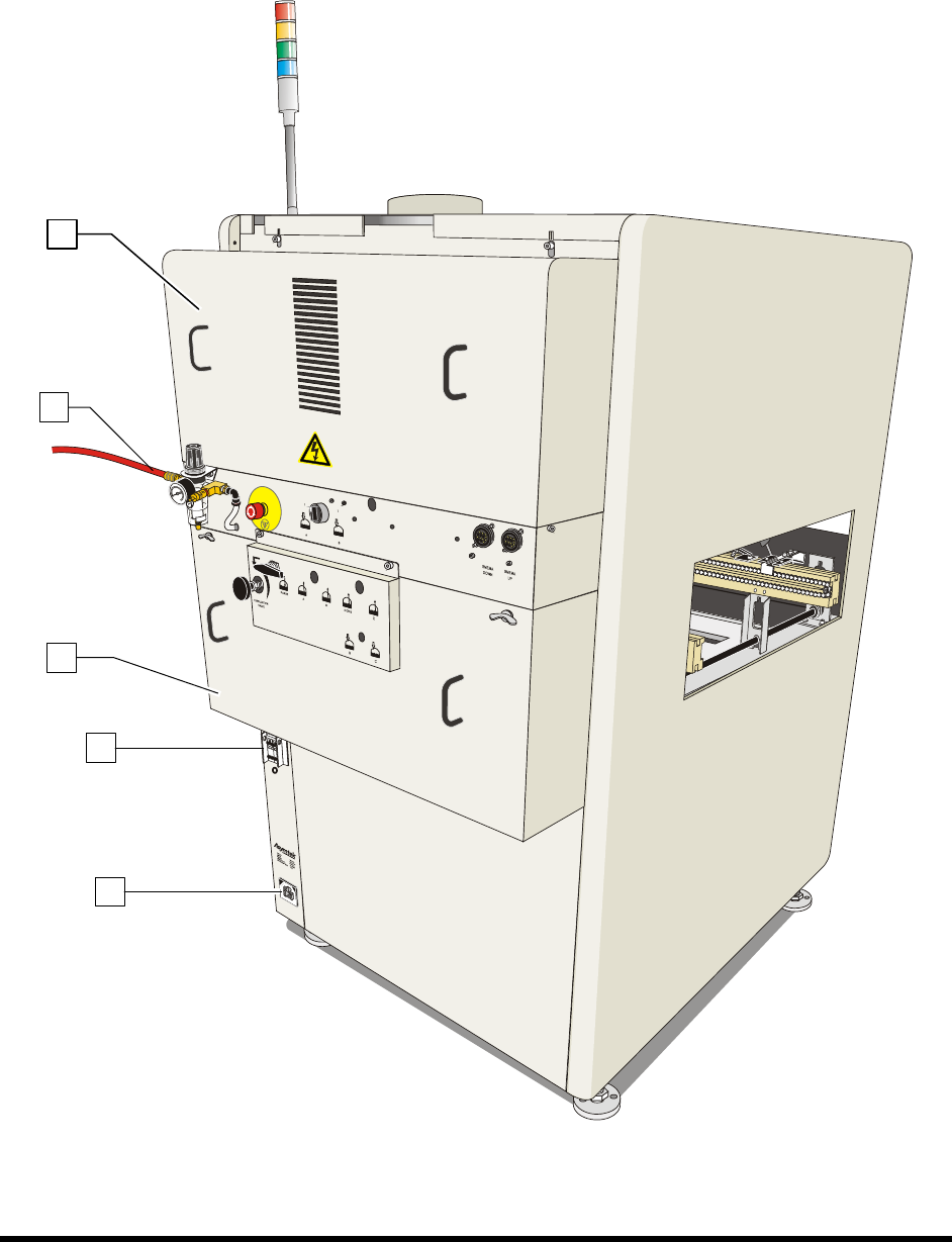
1- 16 Introduction 1.12.2 Rear Vie w Featu res Below are functional d escriptions of SL -940 E/SL - 941E Series components show n in Figur e 1-8. Figure 1-8A 1 3 2 5 4
Introduction 1-15
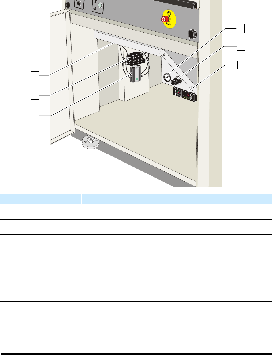
1.12.1.4 Front Cabinet
Below are functional descriptions of SL-940E/SL-941E Series Conformal Coating System components
shown in Figure 1-7.
Item Name Description
1
Reservoir Pressure
Gauge
The Reservoir Pressure Gauge displays the air pressure supplied to the
fluid reservoir and solvent reservoir.
2
Reservoir Pressure
Regulator
The Reservoir Pressure Regulator controls the air supplied to the fluid
reservoir and solvent reservoir.
3
Laser Fan Width
Control Amplifier
(optional)
Laser Fan Width Control provides closed-loop control of the conformal
coating process, automatically compensating for variables within the
process environment that can affect fluid fan width.
4 USB Hub
The USB Hub distributes USB information from the computer to the Main
PWA, Conveyor PWA, and other components.
5
Computer Power
Supply
The Computer Power Supply supplies power to the laptop computer.
6 Spill Pan
The spill protects the dispensing system from fluid spills and overspray. The
pan is removable for ease of cleaning and is interlocked for safety.
Figure 1-7 Front Cabinet
6
2
3
1
5
4
Introduction 1-17
Figure 1-8B
Item Name Description
1
Electronic/Pneumatic
Enclosure
Allows access to the system electronics and pneumatics.
2 Main Air Inlet Connects the coating system to the facility air supply.
3
Fluid System
Enclosure
Houses the purge valve, circulation valve, pump, filter assembly, fluid
regulator, and fluid heater.
4
Main Power Circuit
Breaker
Controls all electrical power to the entire system including the coating
system and laptop computer.
5 Main Power Inlet
Connects the main power cord from the facility source to the coating
system.
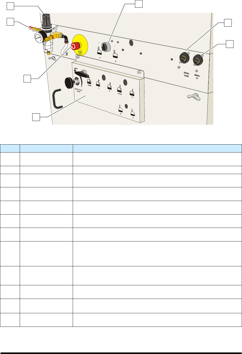
6 Main Air Regulator
Regulates air pressure supplied to the coating system through the main
air inlet.
7 Main Air Gauge
Displays the air pressure to which the main air regulator is set. The
recommended setting is 551 to 620 kPa (80 to 90 psi).
8 Rear EMO
Activating the EMO vents all pressure in the pneumatic system, de-
energizes the robot motors, and cuts power to all system components
except the computer and monitor. Refer to Section 2 - Safety for additional
information.
9
Material Change
Over Panel
Used to switch between a fluid reservoir and solvent reservoir and toggle
the air supplied between the reservoirs. Also houses the circulation valve
and purge valve for the SC-104/105VCS Viscosity Control System.
10
Reservoir Air
Pressure Switch
Three-position switch that toggles the air supplied to Reservoir A, Reservoir
B, or neither.
11
SMEMA Downstream
Connection
Allows for SMEMA communication between the coating system and a
downstream machine such as an unloader.
12
SMEMA Upstream
Connection
Allows for SMEMA communication between the coating system and an
upstream machine such as a loader.
Figure 1-8 Rear View
6
7
8
11
12
9
10