SL940-Install-Ops-Maintenance-7210918_B.pdf - 第98页
5- 18 Operation 5.13 Insta lling the Coating Applic ator Install the coating appl icator as desc ribed in the ap plica ble coating app licator m anua l. SL -940/SL- 941E valve and pneum atic connections a re shown below:…
Operation 5-17
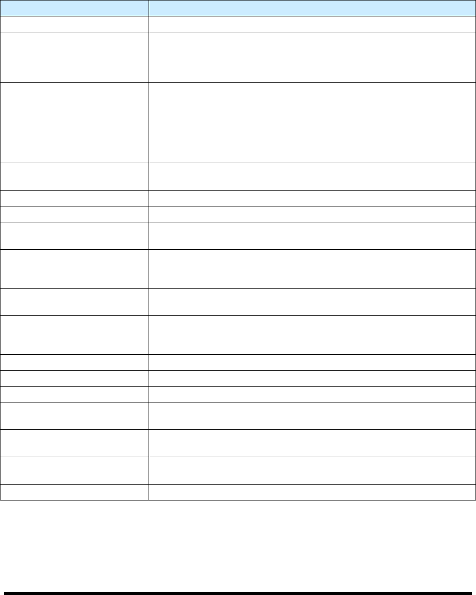
5.12 Daily Routine Procedures
Table 5-2 contains a brief description and instructions for routine procedures that should be performed on
a daily basis before and after operating the coating system.
Table 5-2 Daily Routine Procedures
Procedure Description
STARTUP
Check Main Air Pressure
Ensure that the main air pressure is properly adjusted. If necessary,
adjust the main air pressure as described in 5.10.1 Main Air Regulator
and Gauge. Record the proper setting on the Daily Routine Checklist for
daily reference.
Check Reservoir Pressure
Ensure that the reservoir pressure is properly adjusted. If necessary,
adjust the fluid pressure as described in 5.10.2 Reservoir Pressure
Regulator and Gauge. Record the proper setting on the Daily Routine
Checklist for daily reference.
NOTE Refer to the manual for your specific coating applicator
for appropriate fluid pressure settings.
Verify Exhaust Connection
Verify that the Exhaust Vent is properly connected to the facility exhaust
system ductwork. Refer to 4.5 Exhaust Connection.
Check Ventilation Airflow Verify ventilation holes are clear from obstructions.
Fill Fluid Reservoir
Fill the Fluid Reservoir as described in 5.14 Filling the Fluid Reservoir.
Inspect Hardware
Inspect coating system for broken, loose, worn, or missing hardware.
Replace or repair as necessary.
Fill Solvent Cup
Make sure that the solvent cup is filled with a clean supply of the
appropriate solvent and is properly placed for the selected coating
program.
Inspect Electrical and
Pneumatic Lines
Inspect coating system for broken, loose, or frayed electrical and
pneumatic lines. Replace as necessary.
Inspect Conveyor
Inspect conveyor rollers, bearings, and chain for surface damage.
Ensure that no foreign material adheres to surfaces. Clean and replace
as necessary.
Verify Material Temperature Verify the material temperature, if applicable.
Perform Characterization
Perform a characterization if necessary. Refer to 6.14 Characterization.
SHUTDOWN
Remove Workpieces
Remove all workpieces and foreign objects from the dispensing and
conveyor areas.
Flush Fluid System
Flush the fluid system. See 5.15 Changing Material/Flushing Fluid
System.
Clean Coating System
Clean all surfaces of the coating system (doors, side panels, Front
Panel, part sensor, etc.).
Clean Nozzle Refer to the manual for your specific coating applicator for instructions.
5-18 Operation
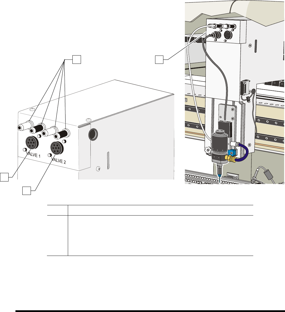
5.13 Installing the Coating Applicator
Install the coating applicator as described in the applicable coating applicator manual. SL-940/SL-941E
valve and pneumatic connections are shown below:
NOTE Pneumatic connections may vary depending on the coating applicator. Refer to the
applicable coating manual for instructions.
Item Description
1
Pneumatic Connections (4)
2
Valve 1 Electrical Connection
3
Valve 2 Electrical Connection
4 Valve and Pneumatic Connections (SC-400 shown)
Figure 5-11 Valve Electrical and Pneumatic Connections
1
2
3
4
Operation 5-19
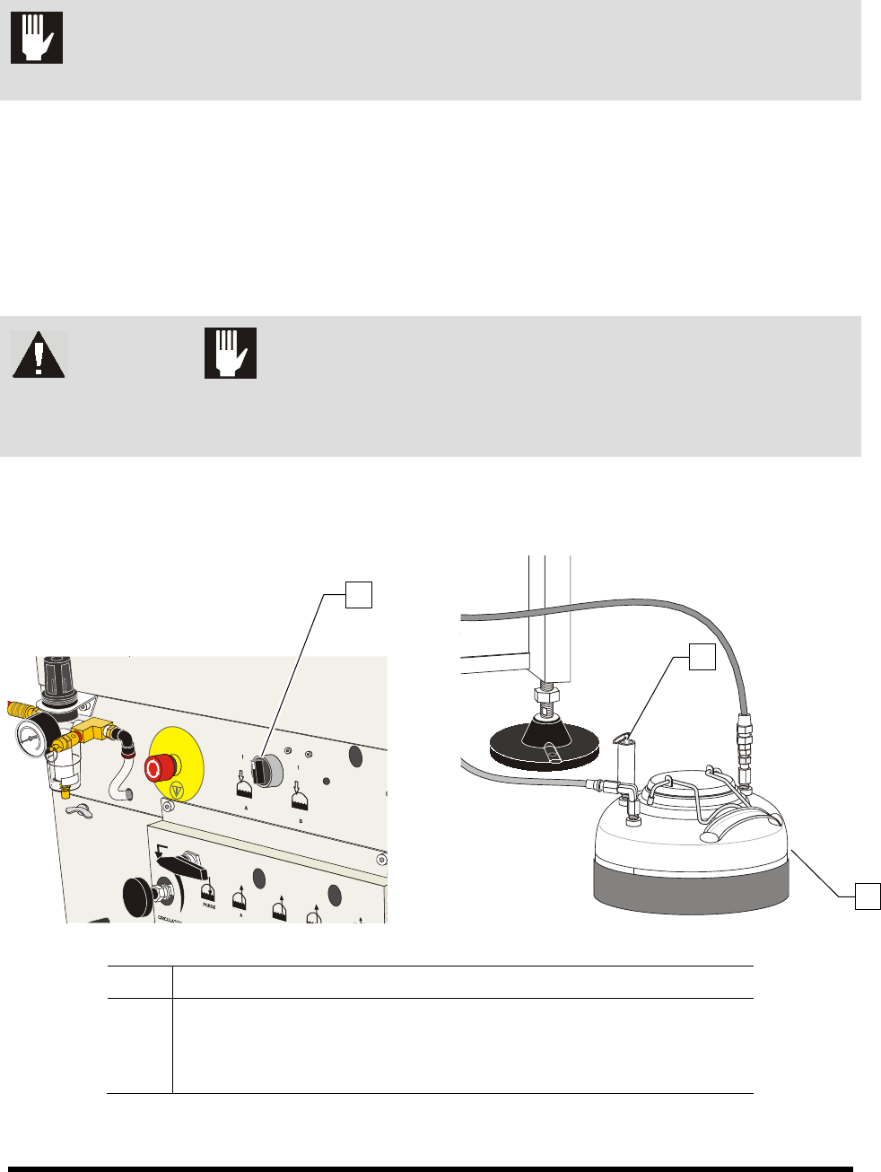
5.14 Filling the Fluid Reservoir
CAUTION! Make sure to observe the fluid level indicator. Never let the coating system run
out of fluid as this may damage the coating applicator.
To fill the Fluid Reservoir:
1. Turn the Reservoir Air Pressure Switch to the OFF
(0) position.
2. Relieve residual pressure in the fluid system by opening the Pressure Relief Valve on the
Fluid Reservoir.
3. Open the lid and check that the reservoir is clean and free from foreign materials.
WARNING! CAUTION!
Solvent vapors may be released when the lid is open. Always wear appropriate
personal protective equipment (PPE) as recommended by facility safety practices
and the material manufacturer’s MSDS.
4. Add fluid up to a maximum of 50 mm (2 in.) below the rim of the opening.
5. Close the lid immediately after filling.
Item Description
1 Reservoir Air Pressure Switch
2 Pressure Relief Valve
3 Fluid Reservoir
Figure 5-12 Filling the Fluid Reservoir
2
3
1