SL940-Install-Ops-Maintenance-7210918_B.pdf - 第99页
Operation 5- 19 5.14 Filli ng the Flui d Reservoir CAUTION! Mak e sure to o bserve the f luid level i ndicator . Nev er le t the co ating s ystem run out of f luid as th is m ay damage t he coati ng app licator . To fill…
5-18 Operation
5.13 Installing the Coating Applicator
Install the coating applicator as described in the applicable coating applicator manual. SL-940/SL-941E
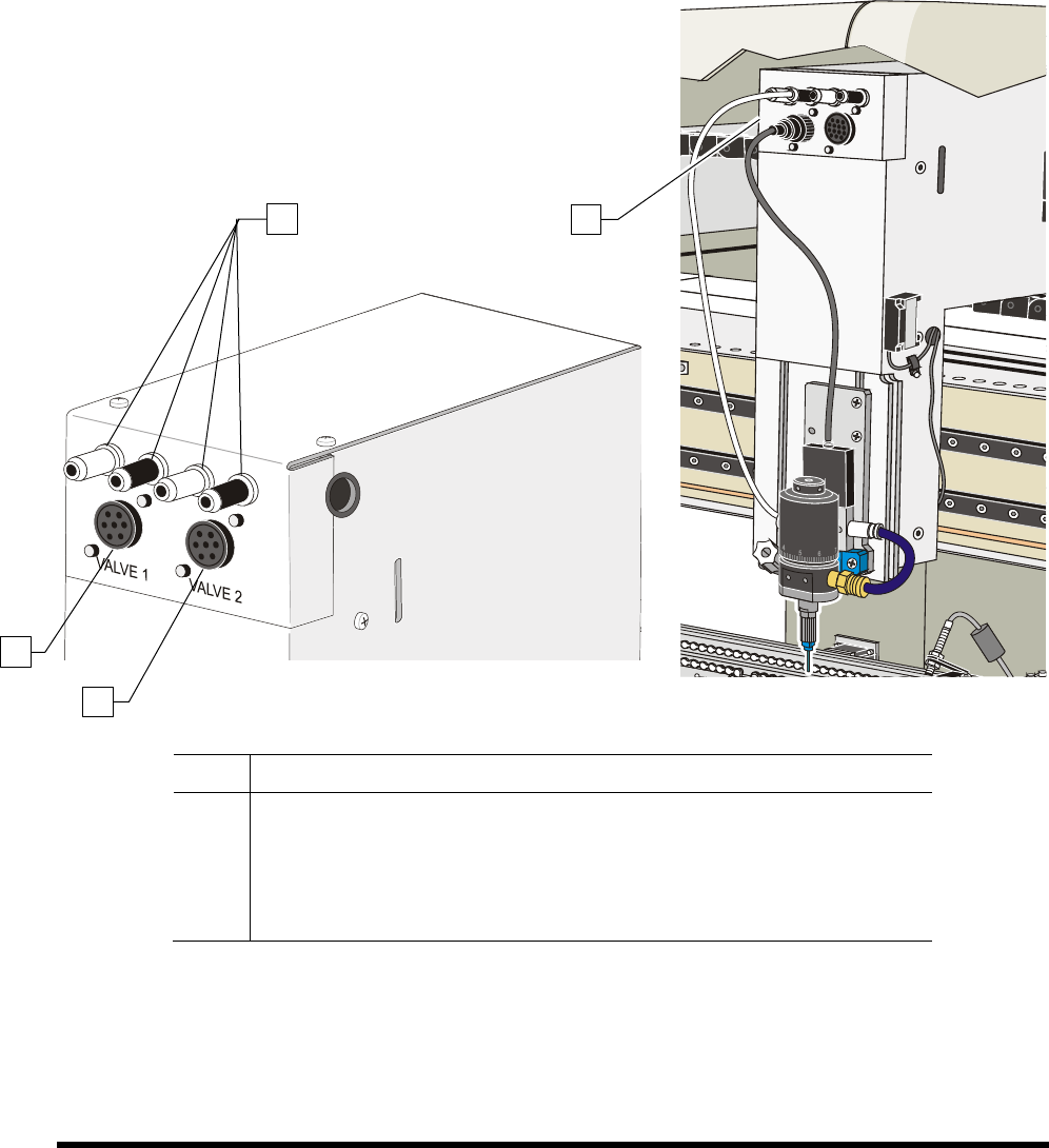
valve and pneumatic connections are shown below:
NOTE Pneumatic connections may vary depending on the coating applicator. Refer to the
applicable coating manual for instructions.
Item Description
1
Pneumatic Connections (4)
2
Valve 1 Electrical Connection
3
Valve 2 Electrical Connection
4 Valve and Pneumatic Connections (SC-400 shown)
Figure 5-11 Valve Electrical and Pneumatic Connections
1
2
3
4
Operation 5-19
5.14 Filling the Fluid Reservoir
CAUTION! Make sure to observe the fluid level indicator. Never let the coating system run
out of fluid as this may damage the coating applicator.
To fill the Fluid Reservoir:
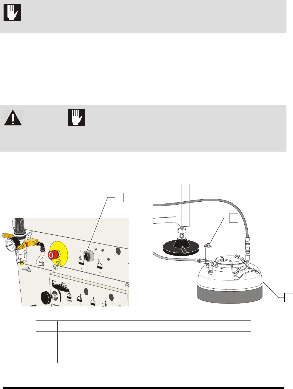
1. Turn the Reservoir Air Pressure Switch to the OFF
(0) position.
2. Relieve residual pressure in the fluid system by opening the Pressure Relief Valve on the
Fluid Reservoir.
3. Open the lid and check that the reservoir is clean and free from foreign materials.
WARNING! CAUTION!
Solvent vapors may be released when the lid is open. Always wear appropriate
personal protective equipment (PPE) as recommended by facility safety practices
and the material manufacturer’s MSDS.
4. Add fluid up to a maximum of 50 mm (2 in.) below the rim of the opening.
5. Close the lid immediately after filling.
Item Description
1 Reservoir Air Pressure Switch
2 Pressure Relief Valve
3 Fluid Reservoir
Figure 5-12 Filling the Fluid Reservoir
2
3
1
5-20 Operation
5.15 Changing Material/Flushing Fluid System
WARNING! CAUTION!
Follow MSDS recommendations for the proper handling and disposal of all
materials when changing material/flushing fluid system. Always wear appropriate
personal protective equipment (PPE) as recommended by facility safety practices
and the material manufacturer’s MSDS.
To change material and flush the fluid system:
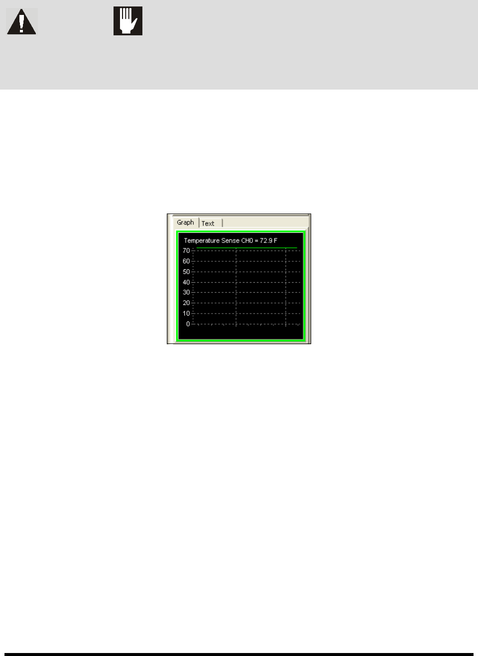
1. If applicable, turn off the heater and allow the fluid to cool for at least fifteen minutes.
To speed up the cooling process, you may circulate the material. The temperature can be
monitored in the Temperature Sense Window (Figure 5-13) in ECXP.
NOTE To view the Temperature Sense Window, the option must be activated in ECXP. See the
ECXP User Guide for instructions.
Figure 5-13 ECXP Temperature Sense Window
2. Reduce fluid air pressure to 7 psi (48 kPa).
Refer to 5.10.3 Fluid Pressure Regulator and Gauge for instructions on adjusting
fluid pressure.
3. Open the purge and filter drain valves.
4. If applicable, adjust the main air pressure to allow the diaphragm pump (Figure 5-14) to
stroke slowly.
The material will drain into the reservoir.
5. When the system is empty, stop the pump by reducing the main air pressure to zero.
6. Flush the system with solvent as described below:
a. Connect the siphoning hose to a container filled with 0.75 liter (1 quart) of solvent.
b. Put the drain hose into the waste container.
c. Start the pump by increasing the main air pressure.
The solvent will purge residual material out of the system.
d. Close the purge valve.