SL940-Install-Ops-Maintenance-7210918_B.pdf - 第70页
4- 10 Pow er - u p an d Testi n g To test th e Conv eyor I/O: 1. Follow the instructions in 4.9 Starting Easy Coat for W indows (ECXP) to sta rt EC XP . 2. Select Edit > Edit Mode from the ECXP Operat or Scr een m enu…
Power-up and Testing 4-9
NOTE Menu choices may vary depending upon system configuration.
4. Select
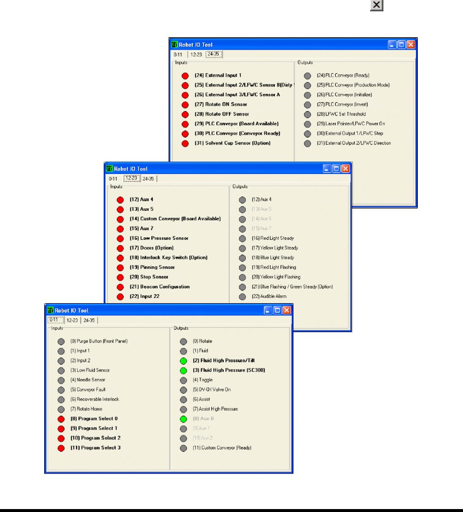
Robot Utilities > IO Tool from the Utilities menu.
A dialog box opens containing a list of Robot inputs and outputs, grouped by tabs
(Figure 4-6).
5. Click on the I/O’s to verify that they are working properly.
Clicking on an output should toggle it ON or OFF. If an item is OFF, the corresponding
button is gray. If it is ON, the corresponding button is green.
When you are done, select
File > Exit from the menu bar or click on to return to the
ECXP Operator Screen.
Figure 4-6 Robot IO Tool
4-10 Power-up and Testing
To test the Conveyor I/O:
1. Follow the instructions in 4.9 Starting Easy Coat for Windows (ECXP) to start ECXP.
2. Select
Edit > Edit Mode from the ECXP Operator Screen menu bar to access the ECXP
Edit Screen.
3. Select
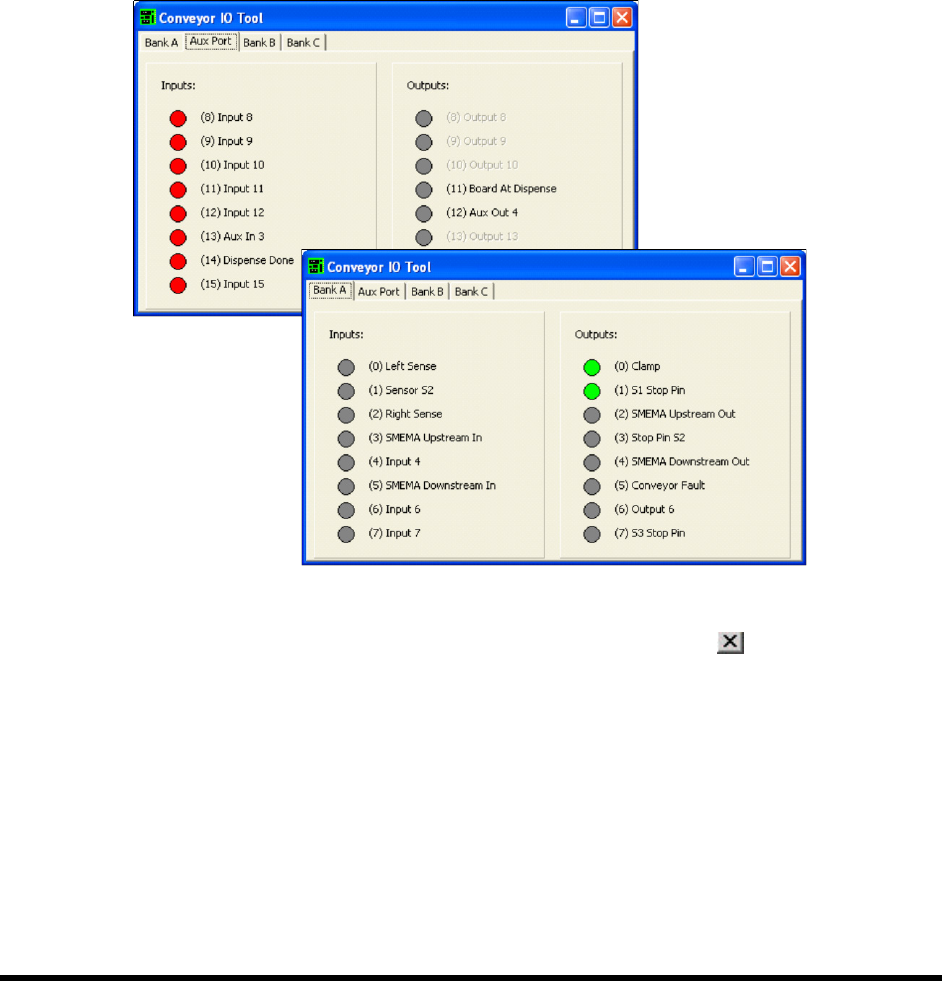
Utilities > Conveyor Utilities > IO Tool from the menu bar.
A dialog box opens containing lists of Conveyor inputs and outputs, grouped by tabs.
4. Click on the I/O’s to verify that they are working properly (Figure 4-7).
Clicking on an output should toggle it ON or OFF. If an item is OFF, the corresponding
button is gray. If it is ON, the corresponding button is green.
Figure 4-7 Conveyor IO Tool
5. When you are done, select File > Exit from the menu bar or click on to return to the
ECXP Operator Screen.
Power-up and Testing 4-11
4.12 Pneumatics
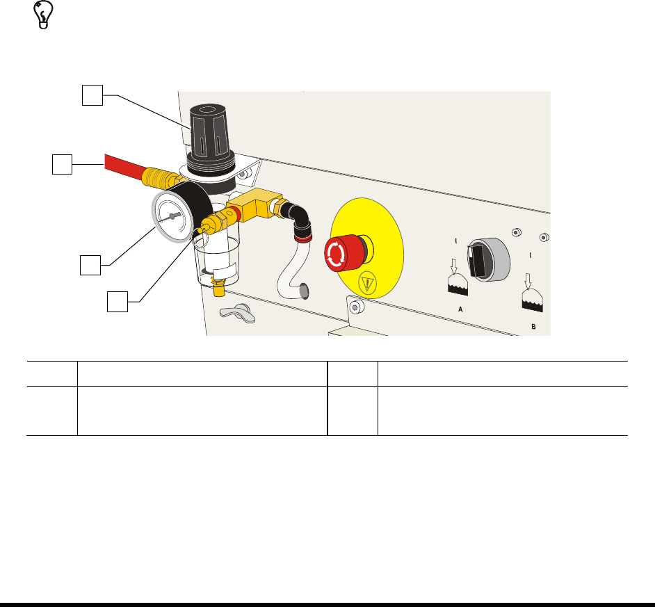
To check the function of the Main Air Regulator and Gauge:
1. Locate the main air regulator at the rear of the coating system (Figure 4-8).
2. Rotate the main air regulator counterclockwise until the Main Air Gauge registers 0 psi.
3. Rotate it clockwise until the main air gauge registers 85-90 psi (586-620 kPa).
If the main air gauge fails to register pressure, verify that the coating system is connected
to the facility air source.
If there is an air leak, identify the source, shut off the facility air, and fix the leak before
proceeding.
NOTE The regulator assembly is equipped with a relief valve to protect the system components.
Increasing the pressure above 95 psi (655 kPa) may trigger the relief valve. If so, reduce
the air pressure below 95 psi.
TIP For accurate pressure adjustment, lower the pressure below the desired level and then
increase to the desired pressure.
Item Description Item Description
1 Main Air Regulator 3 Main Air Pressure Gauge
2 Main Air Inlet 4 Pressure Relief Valve
Figure 4-8 Main Air Regulator and Gauge
1
3
4
2