SL940-Install-Ops-Maintenance-7210918_B.pdf - 第126页
6- 18 Configuration a nd C haracte rization 2. Move the robot until the tool tip is above all c ompone nts on the boards y ou are coating , and any other com ponent in the wor k cell w ith whic h th e tool tip could coll…
Configuration and Characterization 6-17
6.12.2.2 Product Frame
Product Frames (See Figure 6-14, Rectangle B) exist within the Base Frame. ECXP uses fixture
constraint coordinates, plus the length and width of the product, to calculate the coordinates of the
Product Frame within the Base Frame. The Product Frame origin is the calculated Main Pattern Edit
Frame.
NOTE A product can be a board or a pallet (carrier) containing one or more boards. If a pallet
is used, the dimensions of the pallet are used to calculate the Product Frame.
6.12.2.3 Pattern Frame
The origin coordinates of patterns (See Figure 6-14, Rectangle C) other than the Main Pattern are
expressed as a set of coordinates in the Product Frame. The pattern origin coordinates are stored in the
Pattern Edit Frame when the pattern is created.
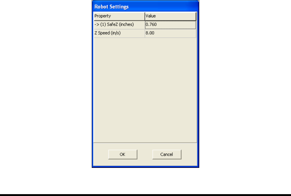
6.12.3 Robot Settings
The Robot Settings dialog box in ECXP is used to set the Safe Z Height and Z-Speed.
To set the Safe Z Height and Z-Speed:
NOTE The Z-Height should be set using the Base Reference Frame which represents the entire
robot travel area. See 6.12.2.1 Base Frame.
1. Click on
Configure > Robot Settings from the ECXP Edit Screen menu bar.
The Robot Settings dialog box opens. See Figure 6-15.
Figure 6-15 Robot Settings Dialog Box

6-18 Configuration and Characterization
2. Move the robot until the tool tip is above all components on the boards you are coating, and
any other component in the workcell with which the tool tip could collide.
3. Select the
Safe Z Height value field.
When you click on the Safe Z Height value field, the
Teach Field button appears.
4. Click on the
Teach Field button.
The value entered is the current Z coordinate of the tool tip, and should be negative.
If you wish to edit this value manually, select the property field and enter a new value.
5. Enter the desired Z-Speed.
6. Click on
OK.
6.13 Bar Code/DataMatrix Scanner Configuration
If your system is equipped with the optional Bar Code/DataMatrix Scanner, you will need to perform a
Scanner configuration. For additional information, refer to the appropriate Scanner User Manual or
contact your Asymtek representative.
6.14 Characterization
NOTE A characterization must be performed for each tool and each coating material used or as
required to ensure quality and consistent dispensing.
Many variables, such as material type, temperature, viscosity, substrate type, robot velocities, and
dispenser response times affect the coating process. Characterization improves coating placement
accuracy and repeatability. The Characterization Wizard helps you adjust program values to compensate
for these variables. The characterization process consists of defining the following values:
• On/Off Response Times
• Coating Height
• Coating Speed (Velocity)
• Coating Width
NOTE All of these variables are interrelated. Make your selections based on the results you want
to achieve. Refer to the ECXP User Guide or Online Help or contact your Asymtek
representative for additional information.
The characterization automatically calculates dispensing ON and OFF times. Characterization
compensates for such variables as:
• Change in air pressure
• Fluid viscosity
• Coating applicator velocity
When you perform a characterization, the coating applicator will dispense three stripes of material. You
will then be prompted to select the best pass for both the start and end values. The values will be stored in
the robot controller. The coating applicator will then dispense three additional stripes of material. These
lines should correspond to the best pass previously selected. This is your characterization.
Configuration and Characterization 6-19
To perform a characterization:
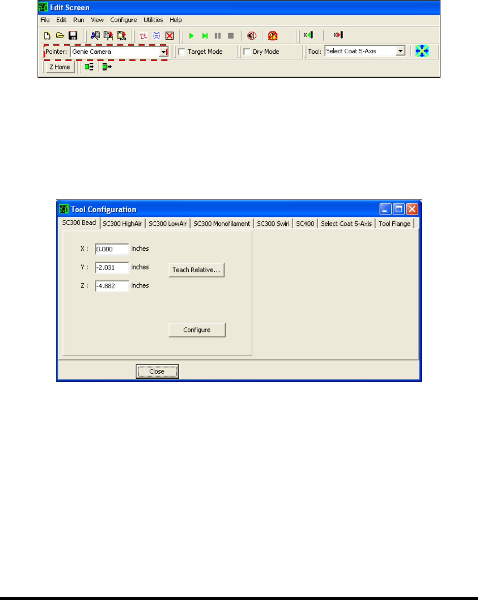
NOTE Make sure you have selected the proper tool as the pointer in the Edit Screen
(Figure 6-16). This is the tool that will be used to teach the positions. If the
system is configured with a Genie Camera or a Laser Pointer and you are going
to use one of these to teach positions, make sure it is selected.
Figure 6-16 Selected Pointer
1. From the Edit screen, click on Configure > Tools.
2. Select the tab for the tool to be configured and then click the
Configure button
(Figure 6-1).
The tabs will vary depending on system configuration.
Figure 6-17 ECXP Tool Configuration
The Conformal Coating Characterization Wizard dialog box shown in Figure 6-18 opens: