SL940-Install-Ops-Maintenance-7210918_B.pdf - 第83页
Operation 5-3 5.7 Conveyor Operat ions 5.7.1 Chain Conveyor The chain convey or transports the work piece into and o ut of the coa ting sy stem . Operation of the conveyor is autom atic during production runs. An opt ica…

5-2 Operation
5.5 Easy Coat for Windows XP (ECXP)
ECXP is Asymtek's proprietary conformal coating software for use in a Windows XP environment. The
software allows the user to develop program files (.ECW file extension), which contain all the robot
moves and I/O operations necessary to coat the workpiece. Refer to 5.17 Loading a Program and 5.18
Running a Program for detailed instructions on how to load and run a dispensing program.
NOTE A workpiece is defined as a board or substrate (PCB, PWB, etc.) or a carrier (pallet, auer
boat, lead frame, etc.) to be dispensed upon.
5.6 Dispensing Operations
All coating operations take place in a workcell. The workcell contains a robot with a coating applicator
mounted on the robot tool arm and a conveyor or adjustable tooling rails.
5.6.1 Robot Concepts
5.6.1.1 Home
The home position of the robot is a known position within the workspace defined by X, Y, and Z
coordinates. It is located at the front left of the workcell.
5.6.1.2 Robot Motion
Robot moves are specified as coordinates on the X, Y, or Z-axes. If a move combines motion in all three
axes, and the Robot Controller cannot move the robot in the Z-axis at the same time as the X and Y-axes,
then the move is performed (depending on the Safe Z Height setting) as follows:
• If the destination is higher than the starting point, the Z motion is performed first.
• If the destination is lower than the starting point, the Z motion is performed last.
5.6.2 Tool
A tool consists of one of the following: (1) coating applicator and nozzle, (2) teach camera, or (3) laser
pointer for programming.
5.6.2.1 Tool Offset
The tool offset is the X, Y, and Z distance from the robot's lower tooling pin to the tool tip (the end of the
nozzle). Robot position is calculated using the coordinates of the tooling pin plus the offset. Refer to
6.12 Robot Configuration to establish Tool Offsets.
5.6.2.2 Safe Z Height
This is the height below which the tool tip cannot go when moving in the workcell. It prevents the tool tip
from colliding with a board component, a fixture, or the conveyor. The Safe Z Height is set in the ECXP
program. Refer to 6.12 Robot Configuration to set the Safe Z Height.
5.6.3 Fixture
Fixture is defined as the location inside the work area used as a consistent and repeatable point for
positioning and queuing the product that will be coated. Refer to 6.9 Fixture Configuration.
Operation 5-3
5.7 Conveyor Operations
5.7.1 Chain Conveyor
The chain conveyor transports the workpiece into and out of the coating system. Operation of the
conveyor is automatic during production runs. An optical sensor detects the part as it arrives, triggering
the Conveyor Controller Module to activate the stop pin to stop the part at the correct location. Board pins
in the dispense zone secure the part in place during fluid dispensing.
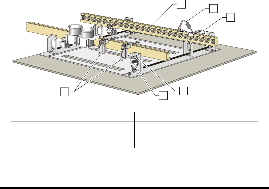
5.7.1.1 Conveyor Adjustments
The conveyor should not need adjustment during normal operation. However, during programming, or
when replacing conveyor parts or changing the type/size of the workpiece, you may need to move the
board pins left or right, or adjust the distance between the conveyor rails.
To manually adjust the distance between conveyor rails:
1. Loosen the Width Adjustment Clamp (Figure 5-1).
2. Manually turn the hand crank clockwise or counterclockwise as needed.
Turning the hand crank clockwise increases the distance between the rails.
Turning the hand crank counterclockwise decreases the distance between the rails.
3. When you are satisfied with the distance between the rails, tighten the Width Adjustment
Clamp.
Item Description Item Description
1 Conveyor Rails 4 Conveyor Adjustment Clamp
2 Board Sensor 5 Hand Crank
3 Stop Pin 6 Board Pins
Figure 5-1 Manual Conveyor Width Adjustment
1
5
4
2
3
6

5-4 Operation
5.8 Detailed Operation (SL-940E)
During operational setup of the SL-940E inline system, the part enters the system using SMEMA
(Surface Mount Equipment Manufacturers Association) handshakes. It moves to the dispensing area
where the conformal coating is applied and then exits the system. Conformal coating application
programs are created using the Easy Coat for Windows XP (ECXP) software installed on the system.
5.8.1 Coating Process
A typical SL-940E (conveyorized) conformal coating process is described below. See Figure 5-2 for
additional details. Setup and programming procedures are not included in the description.
1. A part enters the system from an upstream system.
A SMEMA handshake with upstream machine signals coating system is ready for a workpiece. The
(standard) chain conveyor carries the board by the edges into the dispensing area. A stop pin engages
to stop the board.
2. The part stops in the coating area.
A photoelectric sensor detects the presence of the board. The conveyor indexes the part according to
SMEMA standards. Pneumatically actuated board pins lower into holes in the board to secure it
precisely in place for accurate fluid dispensing.
3. Conformal coating is applied.
The conformal coating fluid is applied to the board, according to a preprogrammed coating pattern.
Refer to the Easy Coat for Windows User Guide for detailed information.
4. The part moves to a downstream system.
When coating is complete, the stop pin disengages, a SMEMA handshake occurs, and the part moves
to the downstream system. Another part is loaded and carried into the dispensing area.