SL940-Install-Ops-Maintenance-7210918_B.pdf - 第148页
8-4 Troubleshoot ing 8.4.4 Vision Sy stem Table 8-4 Vision S ystem T roubleshoot ing Sy mptom Possible C ause Recov ery No Image (ECXP display w indow is a solid pink color) Camera not connec ted Verify ca mera cable is …
Troubleshooting 8-3
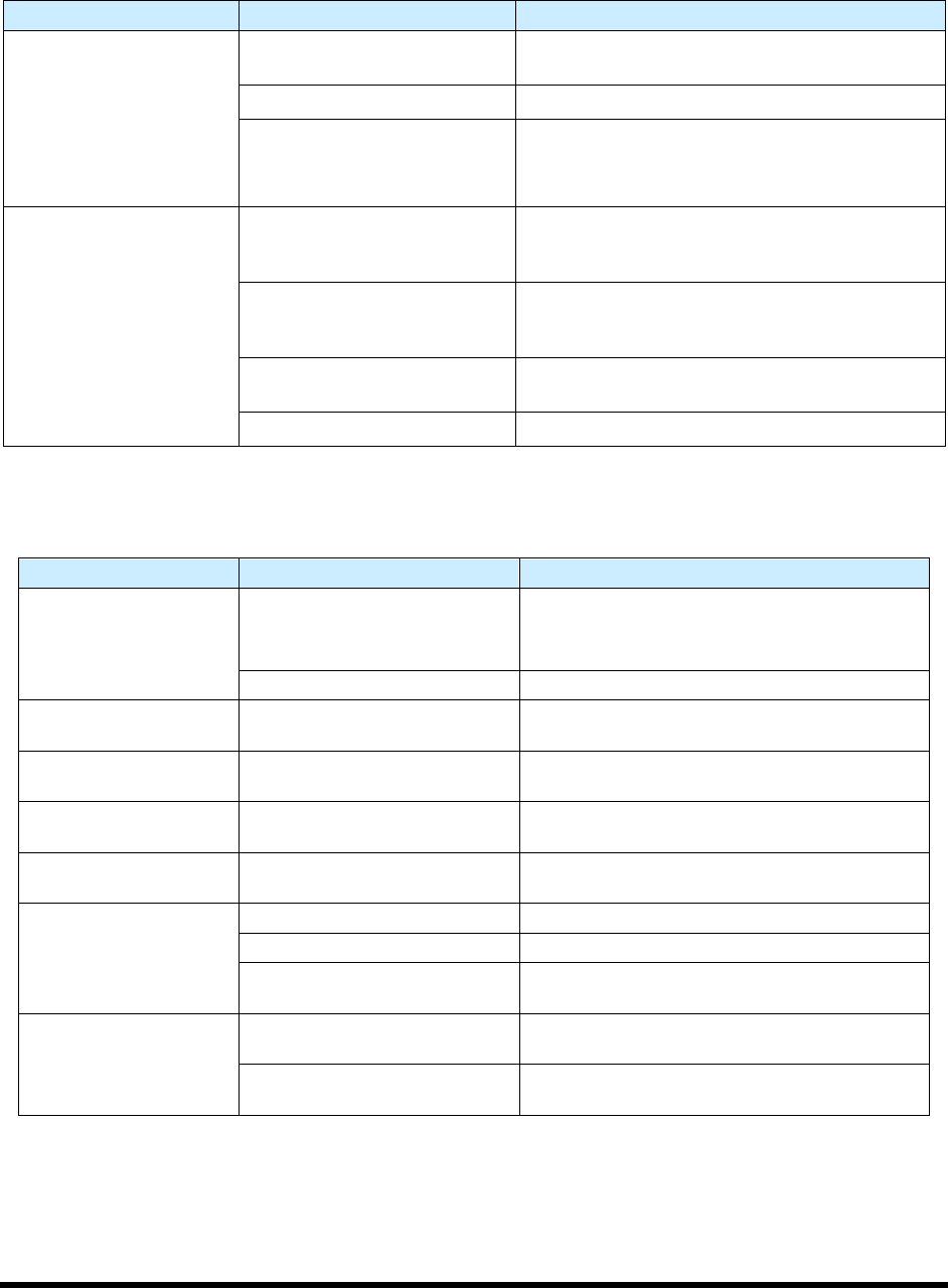
8.4.2 Pneumatics
Table 8-2 System Pneumatic Troubleshooting
Symptom Possible Cause Recovery
No air pressure
System not connected to facility
air supply
Connect the main air inlet to a facility air supply.
Main air regulator off Verify main air regulator is set properly.
Reservoir air regulator off
1. Check reservoir air; secure connections if
necessary.
2. Verify reservoir air regulator is set properly.
No fluid pressure
Nozzle is clogged
Remove nozzle, visually verify that it is clogged.
See the applicable coating applicator manual for
cleaning instructions.
Not enough fluid pressure or no
fluid pressure
Increase fluid pressure. If equipped with material
change over option, verify valves are set to correct
reservoir.
Micro-adjust knob is fully
closed
Open micro-adjustment to characterized setup
value (value between 1 and 12 marks of turn).
ECXP not started Start ECXP.
8.4.3 Conveyor
Table 8-3 Conveyor Troubleshooting (
Symptom Possible Cause Recovery
Chain will not move
EMO button has been activated
1. Turn the EMO button clockwise until it pops
back into position.
2. Press
ON (l) on the operator’s console.
Conveyor Controller malfunction Call a trained service technician.
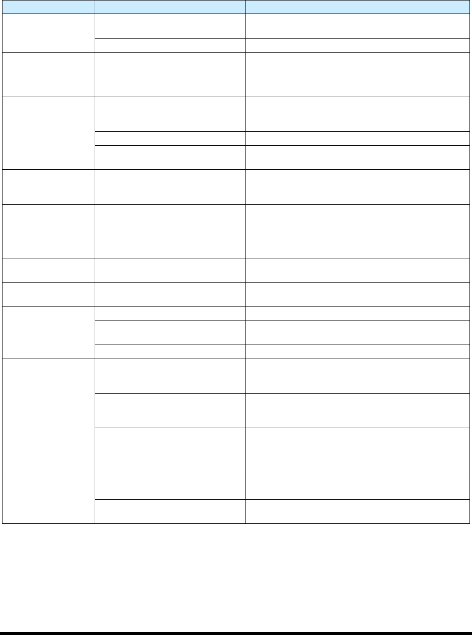
Stop pins, board pins, or
bar clamps do not work.
Air pressure too low
Check main air pressure (80 to 90 psi) and
conveyor air pressure (30 to 40 psi).
No upstream or
downstream interface.
Varies Call a trained service technician.
Part sensor not sensing
when board is present.
Sensor is dirty, not active, or
needs to be adjusted
Clean part sensor, check sensor I/O, or adjust
sensor sensitivity.
Board will not index after
dispensing
No SMEMA signal from
downstream system
Call a trained service technician.
Board will not move to
correct position
Stop pin not receiving air Call a trained service technician.
Part sensor dirty Clean part sensor.
Conveyor rails too close
together
Adjust width between conveyor rails.
Conveyor chain
movement is erratic or
unsteady.
Accumulated debris in chain
Use an airgun or dry, clean cloth to remove
debris from the conveyor chain.
Conveyor chain is loose
Tighten chain by repositioning conveyor motor
(motor weight provides adequate tension).
8-4 Troubleshooting
8.4.4 Vision System
Table 8-4 Vision System Troubleshooting
Symptom Possible Cause Recovery
No Image (ECXP
display window is a
solid pink color)
Camera not connected
Verify camera cable is securely connected to the
connector on the top of the camera.
Faulty camera cable Replace camera cable.
CorAcq Error on
Startup
Camera software did not connect
to camera before ECXP was
started.
Close ECXP and wait until Device available icon is
present in toolbar at lower right corner of screen. If
necessary, right click on device IP error icon and left
click on “find devices”.
Camera LEDs are
OFF
Camera not connected
Verify camera power cable is securely connected to
the connector on the top of the camera and to the
accessories/main board in the Electronics Pan.
Faulty camera cable Replace camera cable.
Machine is not receiving power
Make sure that machine is plugged in, power
manager is on, and green power button is lit.
Camera LED
Steady Red
Camera not initialized
It may take several minutes for the camera to acquire
a connection with the laptop. DO NOT attempt to run
ECXP or DALSA programs during this time.
Camera LED Slow
Flashing Red
Camera Initialization problem
1. Shutdown the computer and turn off power to the
machine.
2. Restart the machine, and then the computer.
3. If necessary, contact a service technician.
Camera LED Fast
Flashing Red
Camera overheated Contact a service technician.
Camera LED Fast
Flashing Blue
Ethernet cable disconnected
Verify Ethernet cable is securely connected to the
camera and computer.
No Image (ECXP
display window is
dark or black)
F-Stop is completely closed. Restore lighting by turning F-Stop ring.
Lens is blocked by foreign matter
Remove and inspect the camera lens. If necessary,
replace lens. See 9.9 Replacing the Camera Lens.
Lens cover is still on. Remove lens cover.
Unfocused image
Substrate is not within height
focus limits of the camera or the
lens is loose
Adjust camera bracket and/or focal ring. See 5.16
Focusing the Camera.
Lens is damaged or there is
foreign matter on the lens
Remove and inspect the camera lens. If lens is
damaged or dirty, contact a service technician. See
9.9 Replacing the Camera Lens.
1.5mm Spacer ring is absent.
Spacer ring should be located
between camera lens and camera
body.
Locate and return spacer ring. See 9.8 Replacing
Camera Lens.
If spacer ring cannot be located, contact service
technician for part number to order replacement.
No monitor display
Computer power switch OFF (0) Turn ON (I) computer power switch.
Computer is asleep.
Press and release computer power switch to wake up
computer.
Parts Replacement 9-1
9 Parts Replacement
9.1 Overview
This section includes general information for ordering recommended spares and replacement parts for
your Select Coat SL-940E/SL-941E Series Conformal Coating System. Part numbers can be found in
Appendix C. This section also contains the following procedures:
• Parts Ordering Information
• Unpacking and Inspecting Replacement Parts
• Gaining Access to Coating System Components
• Replacing Conveyor Chains
• Replacing the Camera Lens
• Replacing Fuses
NOTE This section does not include the removal and replacement of coating applicator
components. Refer to the manual for your specific coating applicator for recommended
maintenance procedures.
9.2 Safety First
Operation of the SL-940E/SL-941E involves heat, air pressure, electrical power, mechanical devices, and
the use of hazardous materials. It is essential that every person servicing or operating the coating system
fully understands all hazards, risks, and safety precautions. Refer to Section 2 - Safety for additional
information.
WARNING! CAUTION!
To ensure optimal performance and safety, it is necessary to install the coating
system and its components in a facility that meets the necessary requirements
listed in Section 10 - Specifications. If you have any questions, please contact
Asymtek Technical Support.
9.3 Record Keeping
The type of service performed should be recorded in the coating system maintenance records. Dates, part
numbers/serial numbers of replaced parts, names of technicians, and other pertinent data should be
recorded.
WARNING! Some part replacement procedures involve the use and disposal of hazardous
materials. Always follow the material manufacturer MSDS, facility requirements,
and local regulations for protection of personnel and disposal of materials.