SL940-Install-Ops-Maintenance-7210918_B.pdf - 第65页
Pow er - up an d Test in g 4-5 4.7 Po w ering On the System To power on the coa ting sy stem : 1. Ve rify that the main power cord is connected to the main power inle t and t he fac il it y power sour ce ( Fi gur e 4-1).…
4-4 Power-up and Testing
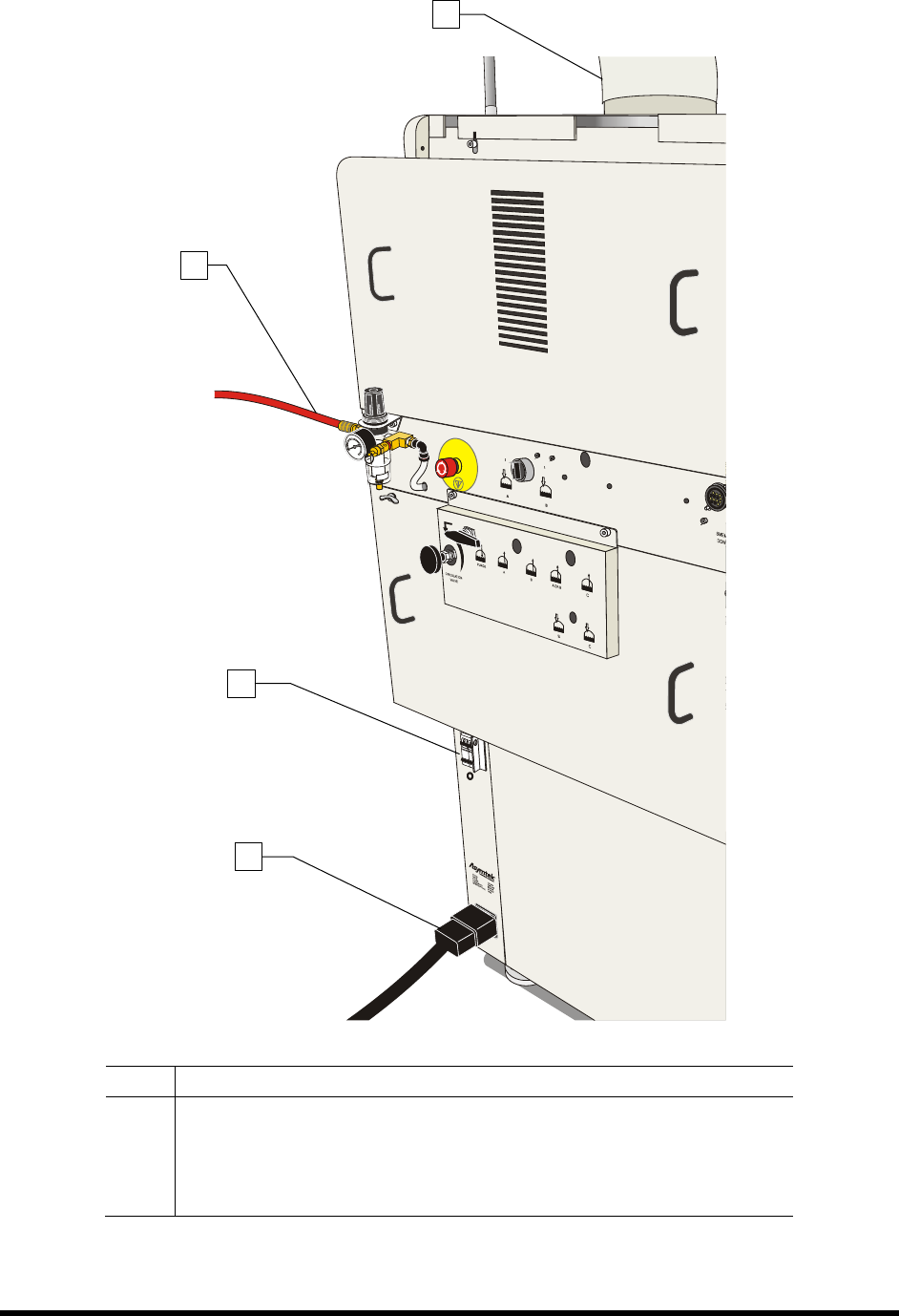
Item Description
1 Exhaust Vent
2 Main Air Inlet
3 Main Power Circuit Breaker
4 Main Power Cord
Figure 4-1 Connecting the Facilities Power and Air Supply (10A Power Manager shown)
2
3
4
1
Power-up and Testing 4-5
4.7 Powering On the System
To power on the coating system:
1. Verify that the main power cord is connected to the main power inlet and the facility
power source (Figure 4-1).
2. Verify that the facility air hose is connected to the main air inlet (Figure 4-1).
3. Verify that the facility exhaust ventilation system ductwork is connected to the Exhaust Vent
Duct (Figure 4-1).
4. Turn the main circuit breaker to the
ON (I) position (Figure 4-1).
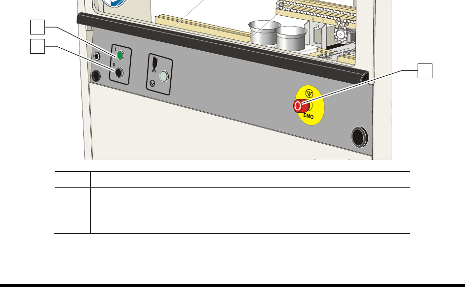
5. Check the EMO buttons to see if they have been activated. If one has been activated,
deactivate it by turning the red knob clockwise until the knob pops out (Figure 4-2).
6. Make sure the interlock signal is not interrupted. Close the coating system hood if applicable.
7. Verify the spill pan in the lower front cabinet is all the way in (Figure 1-7).
8. Turn the laptop computer power button
ON (I).
9. Press the
ON (l) button on the front panel (Figure 4-2).
NOTE During power up, the green start button on the front panel will blink. The coating system
will turn on after an approximate 60-second vent air time delay to ventilate any solvents
in the dispense area. When the system is ready, the green start button will display a solid
light and the light beacon will be green,
The coating system should be in a powered-up state.
The system computer should begin the boot up sequence.
Item Description
1 Start Button
2 Stop Button
3 EMO
Figure 4-2 Front Panel Buttons
1
2
3
4-6 Power-up and Testing
4.8 Camera States
An optional Dalsa-Coreco Genie M640 digital 640 x 480 pixel camera communicates bi-directionally to
the laptop computer via Gigabit Ethernet. After the Genie software package installation, the GigE Server
icon is visible in the desktop taskbar tray area. The icons and descriptions are shown in Table 4-1.
Table 4-1 Genie Camera States
Icon State Description
Device Available
The GigE server tray icon when the Genie device is found. It will
take a few seconds for the GigE Server to refresh its state after the
Genie has obtained an IP address.
Device IP Error
The GigE server tray icon shows a warning when a device is
connected but there is some type of IP error.
Device Not
Available
A red X will remain over the GigE server tray icon when the Genie
device is not found. This indicates a major network issue.
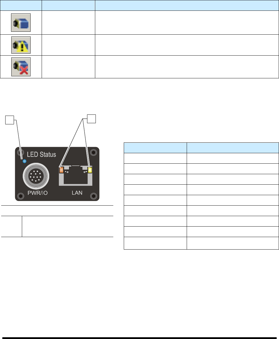
The Genie has one multicolor LED to provide a simple visible indication of camera state. Additionally the
RJ45 has two LEDs for network status conditions (Figure 4-3). LED Status indicators are described in
Table 4-2.
Table 4-2 Camera Status Indicators
LED Status Description
LED's are OFF No Power to Camera
Steady Red Camera Not Initialized
Slow Flashing Red Camera Initialization Problem
Fast Flashing Red Camera Overheating
Steady Blue IP Address Assigned
Item Description
Slow Flashing Blue Waiting for an IP Address
1 Camera Status LED Fast Flashing Blue Ethernet Cable Disconnected
2 Network Status LED Steady Green Application Linked to the Camera
Figure 4-3 Camera LED's (Rear View)
Slow Flashing Green Trigger Acquisition in Progress
1
2