SL940-Install-Ops-Maintenance-7210918_B.pdf - 第178页
在线预览 SL940-Install-Ops-Maintenance-7210918_B.pdf PDF 文档。

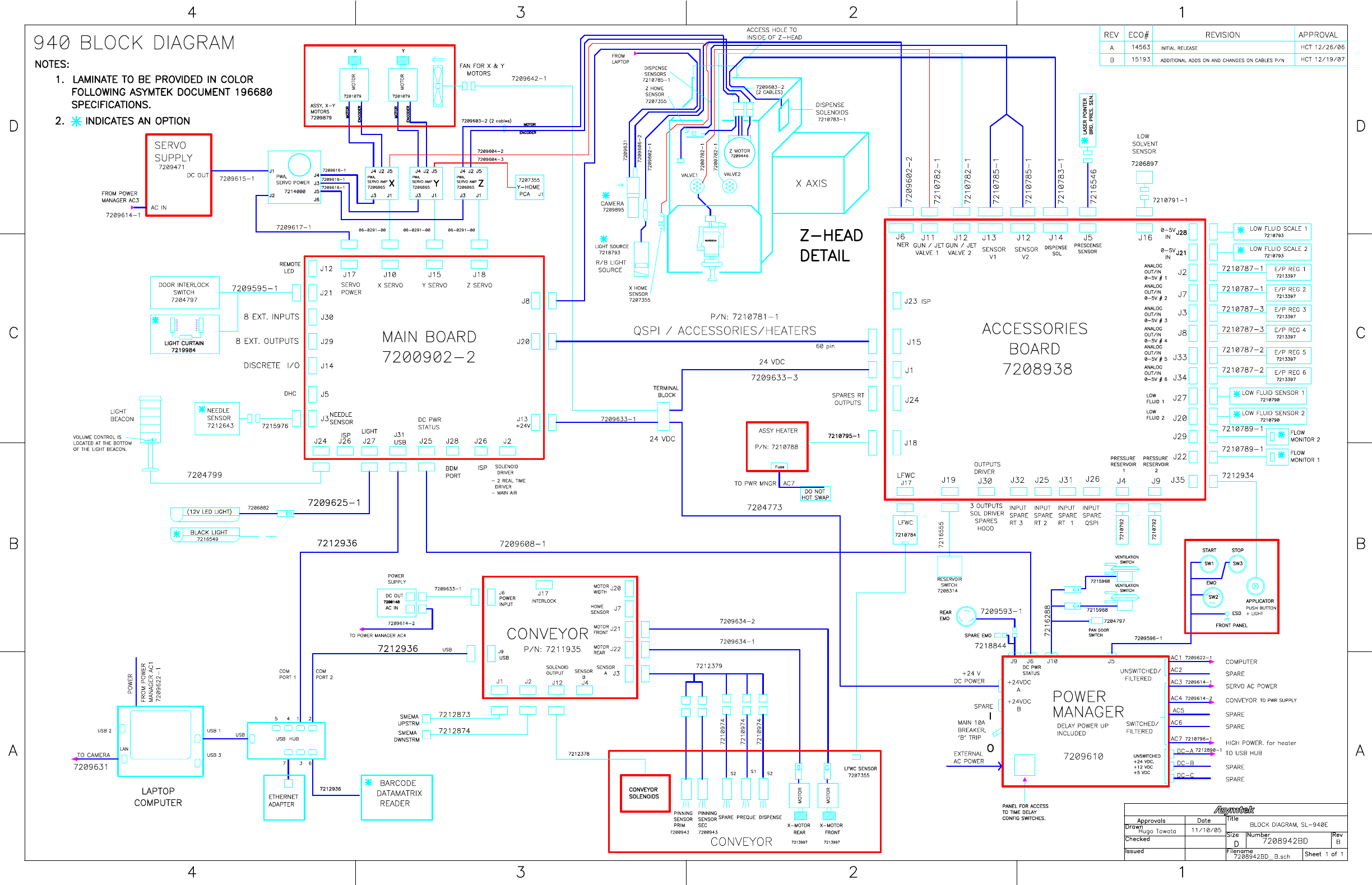
Appendix B - Block Diagrams B-3
Item Name Description
1 AC1-AC2 Breaker Reset Resets the AC1-AC2 circuit breakers
2 AC1 Unswitched Supplies AC power to the computer
3 AC2 Unswitched Spare unswitched DC outlet
4 AC3 EMO Switched Supplies AC power to the servo power supply
5 AC4 EMO Switched Supplies AC power to the USB power supply
6 AC5 EMO Switched (spare)
7 AC6 EMO Switched (spare)
8 AC8 EMO Switched Supplies power to the optional conveyor module CV2
9 AC8 Breaker Reset Resets the AC8 circuit breaker
10 AC3-AC6 Breaker Reset Resets the AC3-AC6 circuit breakers
11 Power Controls Connects to the Start, Stop, and EMO power controls
12 DC Power Status Provides machine power status to the main PWA electronics
13 +24 VDC Switched
Supplies DC power to the terminal block located on the lower e-
pan
14 +24 VDC Switched Spare switched DC outlet
15 Rear EMO Connect to the rear EMO switch
16 Time Delay Config
Access panel for configuration switches that change between
"Time Delay" and "Instant On" power up characteristic.
17 Vent Air Switch Connects to the vent air switch (bypassed in default configuration)
18 AC7 Breaker Reset Resets the AC7 circuit breaker
19 AC7 EMO Switched Supplies power to the conveyor module CV1
Figure B-1 Power Manager Connections
CIRCULATING
HEATER