SL940-Install-Ops-Maintenance-7210918_B.pdf - 第50页
在线预览 SL940-Install-Ops-Maintenance-7210918_B.pdf PDF 文档。
Safety 2-15
2.14 Light Beacon
The Light Beacon is a device that displays system status and can warn the operator when fault conditions
exist. The beacon has red, yellow, green, and blue lights that can be solid or flashing. The beacon also has
an audible alarm. Table 2-3 provides possible reasons for each color indication.
Software and hardware share control of the beacon lights. Sometimes, hardware-driven displays override
those caused by software conditions and sometimes software-driven displays override those caused
hardware conditions. Safety critical conditions always have priority. Flashing light software commands
have priority over solid light commands.
NOTE Light beacon action can be custom configured using the beacon control feature. Refer
to the Easy Coat User Guide for details.
Refer to Section 8 - Troubleshooting for suggested recovery from common fault
conditions.
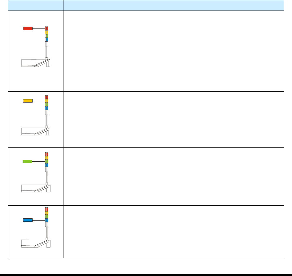
Table 2-3 Beacon Color Indications
Beacon Color System Status
RED
ALERT
All motion, outputs, dispensing valve, and motion controls are disabled until
the fault is cleared.
One of the following conditions may exist:
A. Solid – Emergency stop condition.
B. Flashing – Exhaust failure. Loss of power to machine. Software driven
error message is displayed on the computer monitor.
C. Solid or Flashing - Software has been configured to display a solid or
flashing red light.
YELLOW
CAUTION
System in a low power state or lacks sufficient air pressure.
One of the following conditions may exist:
A. Solid – Door is open (Interlock activated).
B. Solid or Flashing - Software has been configured to display a solid or
flashing yellow light.
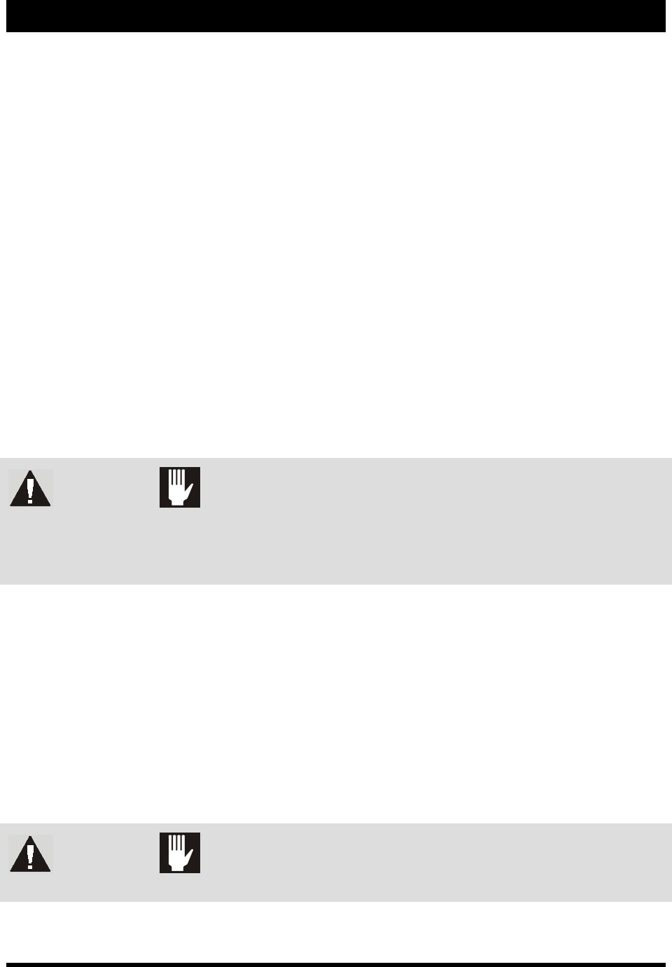
GREEN
OPERATION
One of the following conditions may exist:
A. Solid – The system is fully operational with the door closed.
B. Solid or Flashing – Software has been configured to display a solid or
flashing green light.
BLUE
USER DEFINED
A. Solid – When low fluid is detected.
B. Flashing – Software has been configured to display a flashing blue light.
Installation 3-1
3 Installation
3.1 Overview
This section describes installation procedures for the Select Coat SL-940E/SL-941E Series Conformal
Coating System and covers the following topics:
• Uncrating and Placing the Coating System
• Unpacking the Coating Area
• Leveling the Coating System
• Installing the Light Beacon
• Installing the Laptop Computer
• Installing the Optional Genie Camera
• Anchoring the Coating System
3.2 Safety First
Operation of your SL-940E/SL-941E Series Conformal Coating System involves heat, air pressure,
electrical power, mechanical devices, and the use of hazardous materials. It is essential that every person
servicing or operating the coating system fully understands all hazards, risks, and safety precautions.
Refer to Section 2 - Safety for additional information.
WARNING! CAUTION!
To ensure optimal performance and safety, it is necessary to install the coating
system in a facility that meets the necessary requirements listed in Section 10 -
Specifications. If you have any questions, please contact Asymtek Technical
Support.
3.3 Uncrating and Placing the Coating System
Tools and Materials Needed:
•
1/2 inch wrench
•
Band Cutter
•
9/16 inch wrench
•
Phillips Screwdriver (included in tool kit)
•
Personal Protective Equipment •
1 ½-inch wrench (included in tool kit)
•
Hammer
•
Forklift
•
Flat Bar •
Level
WARNING! CAUTION!
Installation procedures should only be performed by a trained service technician.