SL940-Install-Ops-Maintenance-7210918_B.pdf - 第48页
2- 14 Safety 3. Rotate th e Main A ir Pres sure k nob counterclockw ise until the gaug e reads 0 psi an d then disconnect the m ain air supply by the quick release fit ting. 4. Install an approv ed, keyed lock on the loc…

Safety 2-13
2.11 Interlock
The interlock is an electronic connection that immediately cuts the power to any motion and pneumatic
actuators. If the dispensing area hood is opened during dispensing, the interlock is activated and all
dispensing activity immediately stops to protect the operator from injury. There is a second interlock
device inside the front cabinet on the spill pan to ensure an appropriate ventilation path when the drawer
is pulled out for maintenance.
2.11.1.1 Interlock Shutdown
When an interlock shutdown occurs, the motor power turns OFF, the system loses master references, and
the red beacon light illuminates. The program WILL NOT resume from where it stopped.
To recover from a shutdown triggered by the Interlock:
1. Close the dispensing area hood.
2. Restart the dispensing program. See 5.17 Loading a Program and 5.18 Running a Program.
2.12 Service Shutdown
Before performing any service or parts replacement, the coating system should be shut down as follows:
1. Shutdown the coating system as described in 5.11.2.4 Service Shutdown.
2. Perform a “Lockout/Tagout of Electrical and Pneumatic Energy” as described below.
2.13 Lockout of Electrical and Pneumatic Energy
Companies may differ in their Lockout/Tagout (LOTO) procedures and requirements, and it is the
responsibility of the end user to determine compliance with local safety procedures. The purpose of any
LOTO effort is to help avoid injury or coating system damage due to unexpected energizing of
equipment, start up, or the release of stored energy during repair, maintenance, and operation of
equipment. Situations where LOTO practices may be employed on the SL-940E/SL-941E include:
• Adjusting cables, belts, pulleys, or moving parts
• Servicing bearings or motors
• Troubleshooting, servicing, or replacing electronic components or assemblies
• Troubleshooting, servicing, or replacing pneumatic components or assemblies.
Situations where LOTO practices might not be required are when troubleshooting electrical, pneumatic,
or hydraulic components or assemblies that make de-energizing the whole system impractical.
Troubleshooting or servicing the SL-940E/SL-941E while powered up and operating should only be
accomplished by fully trained and qualified personnel. There should always be a second person present
when performing maintenance on a system under power.
To lockout/tagout the electrical and pneumatic energy:
1. Turn the Main Power Circuit Breaker on the rear of the system to the
OFF (0) position.
2. Unplug the main power cable from the back of the Power Manager.
2-14 Safety
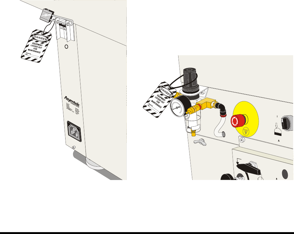
3. Rotate the Main Air Pressure knob counterclockwise until the gauge reads 0 psi and then
disconnect the main air supply by the quick release fitting.
4. Install an approved, keyed lock on the locking flange of the Main Circuit Breaker so it cannot
be turned on; tag it with an approved tag.
Ensure that the owner, date, reason, and estimated time for repair are clearly marked on
the tag.
5. Install an approved lockout clamp and keyed lock onto the power connector so it cannot be
reconnected to the Power Manager, and attach an approved tag.
Ensure the owner, date, reason, and estimated time to repair are clearly marked on the
tag.
6. Install an approved lockout clamp and keyed lock onto the pneumatic fitting so it cannot be
reconnected to the Main Air Regulator, and attach an approved tag. Ensure the owner, date,
reason, and estimated time to repair are clearly marked on the tag.
NOTE Warning tags document the name of the technician taking the equipment out of operation,
the date, and other facility-required information. It is a warning that the equipment cannot
be put back into operation until the authorized technician has removed the tag.
Figure 2-8 Lockout of Electrical Power Figure 2-9 Lockout of Pneumatic Pressure
Safety 2-15
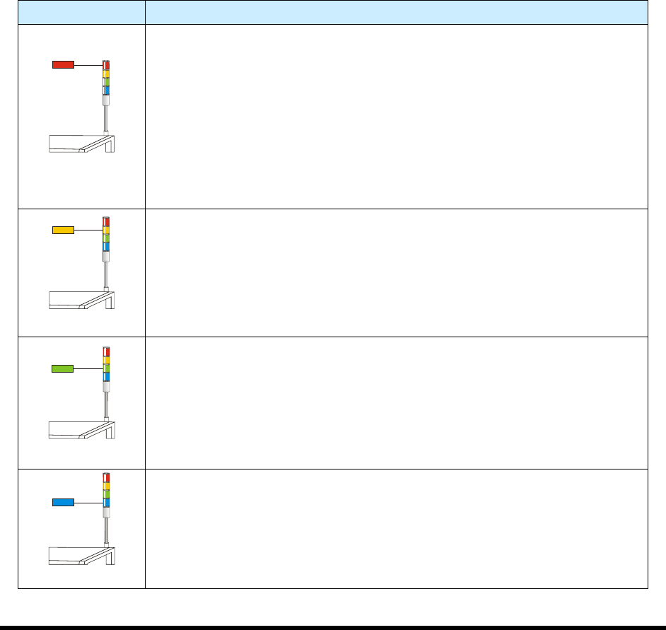
2.14 Light Beacon
The Light Beacon is a device that displays system status and can warn the operator when fault conditions
exist. The beacon has red, yellow, green, and blue lights that can be solid or flashing. The beacon also has
an audible alarm. Table 2-3 provides possible reasons for each color indication.
Software and hardware share control of the beacon lights. Sometimes, hardware-driven displays override
those caused by software conditions and sometimes software-driven displays override those caused
hardware conditions. Safety critical conditions always have priority. Flashing light software commands
have priority over solid light commands.
NOTE Light beacon action can be custom configured using the beacon control feature. Refer
to the Easy Coat User Guide for details.
Refer to Section 8 - Troubleshooting for suggested recovery from common fault
conditions.
Table 2-3 Beacon Color Indications
Beacon Color System Status
RED
ALERT
All motion, outputs, dispensing valve, and motion controls are disabled until
the fault is cleared.
One of the following conditions may exist:
A. Solid – Emergency stop condition.
B. Flashing – Exhaust failure. Loss of power to machine. Software driven
error message is displayed on the computer monitor.
C. Solid or Flashing - Software has been configured to display a solid or
flashing red light.
YELLOW
CAUTION
System in a low power state or lacks sufficient air pressure.
One of the following conditions may exist:
A. Solid – Door is open (Interlock activated).
B. Solid or Flashing - Software has been configured to display a solid or
flashing yellow light.
GREEN
OPERATION
One of the following conditions may exist:
A. Solid – The system is fully operational with the door closed.
B. Solid or Flashing – Software has been configured to display a solid or
flashing green light.
BLUE
USER DEFINED
A. Solid – When low fluid is detected.
B. Flashing – Software has been configured to display a flashing blue light.