编带机说明书-含图纸ttm402.pdf - 第108页
5-10 TM-403 User’s Guide Configure Inspection D292105.16c.fm Configur e Inspection Note: Significant portions of this document ation were provided by: Keyence Cor- poration of America. In order to use the Keyence IV V is…
D292105.16c.fm Connect Vision
Chapter 5: Setup 5- 9
Connect Keyence Monitor
Follow the steps below to connect the Keyence IV-G Camera to the Keyence Monitor.
(See previous section if using the Keyence computer.)
1. Connect the Monitor's Ethernet cable to the Ethernet port on the back of the TM-
402 (A).
2. Connect the Monitor's power cable to the power connection on the back of the TM-
402 (B).
3. Turn the TM-402 ON. The Keyence Monitor will automatically start and open the
Keyence software program.
4. Select Direct Connection, then press Connect to establish a connection between
the Keyence Monitor and the Keyence Camera.
Step 1:
Vision
Setup
CONNECT
MONITOR
A
B
5-10 TM-403 User’s Guide
Configure Inspection D292105.16c.fm
Configure Inspection
Note: Significant portions of this documentation were provided by: Keyence Cor-
poration of America. In order to use the Keyence IV Vision System, the camera
must be configured and set to Run Mode in the Keyence HMI as well as being
enabled on the TM-402 HMI. Please complete the following instructions to cor-
rectly configure the vision system.
Configure Computer
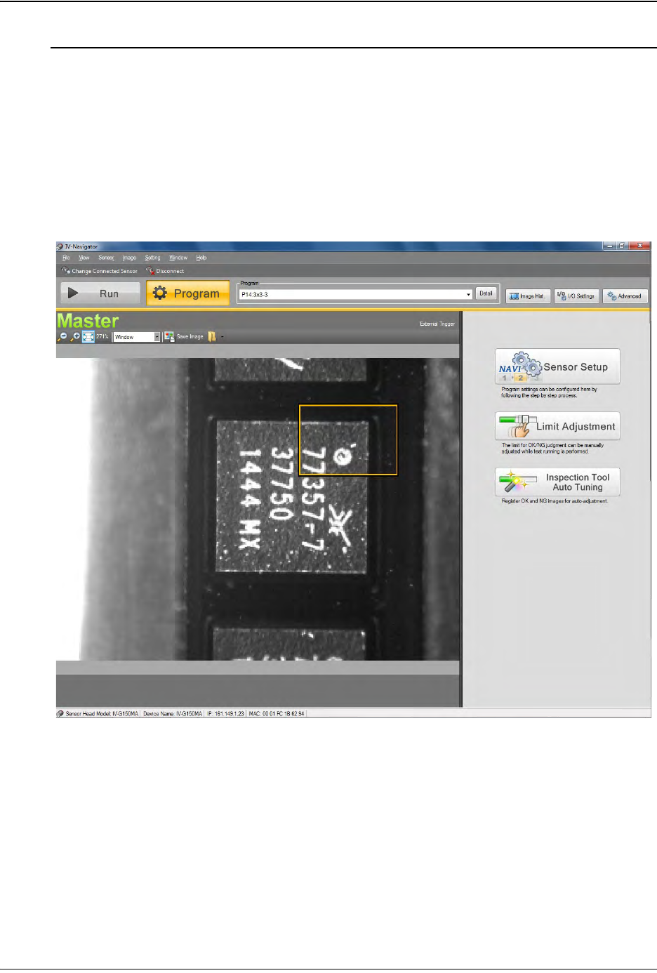
1. Once the connection is complete, the Run/Program window will open. Select
Program.
D292105.16c.fm Configure Inspection
Chapter 5: Setup 5- 11
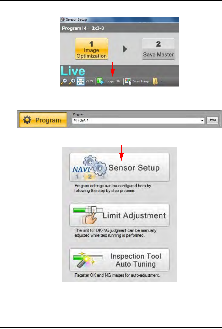
2. Click Trigger ON, then center a part under the camera.
3. Select or create a program from the Program drop-down menu. A yellow Selection
Box will appear over the part image.
4. Click NAVI Sensor Setup.
Step 2:
Vision
Setup
CONFIGURE
COMPUTER