编带机说明书-含图纸ttm402.pdf - 第198页
Appendix A: Sensors A-2 Keyence FS-N11CP & FSN12CP Se nsor Amplifiers D291842.11.fm K ey ence FS-N11CP & FSN12CP Sensor Amplifiers The Keyence FS-N1 1CP and FS-N12CP sensor amplifiers (shown in Figure A.1 below) …

Appendix A: Sensors
Contents
Keyence FS-N11CVP/FS-N12CP Sensor Amplifiers. . . . . . . . . . . . . . . . . .A-2
SMC ZSE30 Vacuum Sensor. . . . . . . . . . . . . . . . . . . . . . . . . . . . . . . . . . . .A-4
Appendix A: Sensors A-2
Keyence FS-N11CP & FSN12CP Sensor Amplifiers D291842.11.fm
Keyence FS-N11CP & FSN12CP Sensor Amplifiers
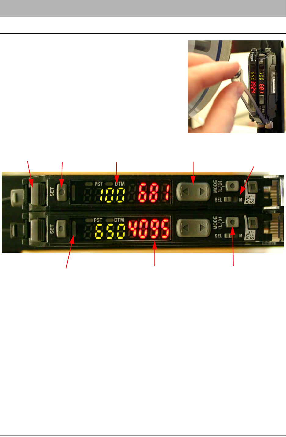
The Keyence FS-N11CP and FS-N12CP sensor amplifiers
(shown in Figure A.1 below) are used on the TM-400 Series
machines for the Low Cover Tape Sensor and the Tape Jam
Sensor. Both amplifiers are mounted on the Cover Tape
Arm. The Low Cover Tape amplifier (FS-N11CP) is located
on the left. The Tape Jam amplifier (FS-N12CP) is located
on the right.
The two amplifiers are designed to be attached electrically
and share power. Otherwise, the two units function indepen-
dently of one another.
Selecting the Output Mode
The FS-N11CP/FS-N12CP sensor-amplifiers can be set to two Output Modes: light-ON or dark-
ON. This determines under what conditions the sensor is triggered and the Operation Indicator is
lit.
In light-ON mode, the sensor will be triggered when the current value (CV) of detected light from
the emitter is higher than the preset value (PV). In dark-ON mode, the sensor is triggered when
the CV of detected light is lower than the PV. Essentially, in light-ON Output Mode the sensor
detects when an obstruction occurs (causing reflected light to increase) and in dark-ON Output
Mode the sensor detects when an obstruction is removed (causing reflected light to decrease).
1. Press the Output Selector button. The CV Indicator will display the current mode.
2. Press the Manual button within 5 seconds of having pressed the Output Selector button.
The Output Mode will be toggled.
Figure A.1
Fiber Lock Lever
Set Button Preset Value (PV) Indicator Manual Button
Output Selector
Operation Indicator Current Value (CV) indicator
Mode Button
Button

Keyence FS-N11CP & FSN12CP Sensor Amplifiers D291842.11.fm
A-3 Appendix A: Sensors
3. The CV Indicator will return to its normal display after 5 seconds have elapsed.
Locking the Keys
It is sometimes desirable to lock the keys of the sensor amplifiers so that the currents settings are
not inadvertently changed.
1. Hold down the Manual button and the Mode button simultaneously for at least three sec-
onds.
2. The CV indicator will display Loc to indicate that the lock is in place.
3. Repeat the same procedure to unlock the keys. The display will flash the message unL.
Two-point Calibration
1. With an obstructing object between the sensors (ideally, a full reel of cover tape), press
and release the SET button. The PV Indicator will be lit.
2. Remove the obstruction between the sensors and press SET again. The amplifier will
return to its normal operating mode. The number shown on the PV Indicator should
change.
3. If the sensor is in dark-ON mode, the operation indicator should be lit while there is an
obstruction between the sensors. If the sensor is in light-ON mode, the operation indica-
tor should be lit while there is no obstruction between the sensors.