编带机说明书-含图纸ttm402.pdf - 第197页
Appendix A: Sensors Content s Keyence FS-N1 1CVP/FS-N12CP Sensor Amplifiers . . . . . . . . . . . . . . . . . . A-2 SMC ZSE30 V acuum Sensor . . . . . . . . . . . . . . . . . . . . . . . . . . . . . . . . . . . . A-4
8-10 TM-401 User’s Guide
General Maintenance Tasks D292105.10a.fm
Loading Track.
The Loading Track should be cleared of dust and
debris after every 40 hours of operation.
Strip the machine, remove the cover tape guide, and brush the dust and debris from the track
with a small, stiff bristled paint brush. Excessive build-up of dirt and debris can cause carrier tape
jams.
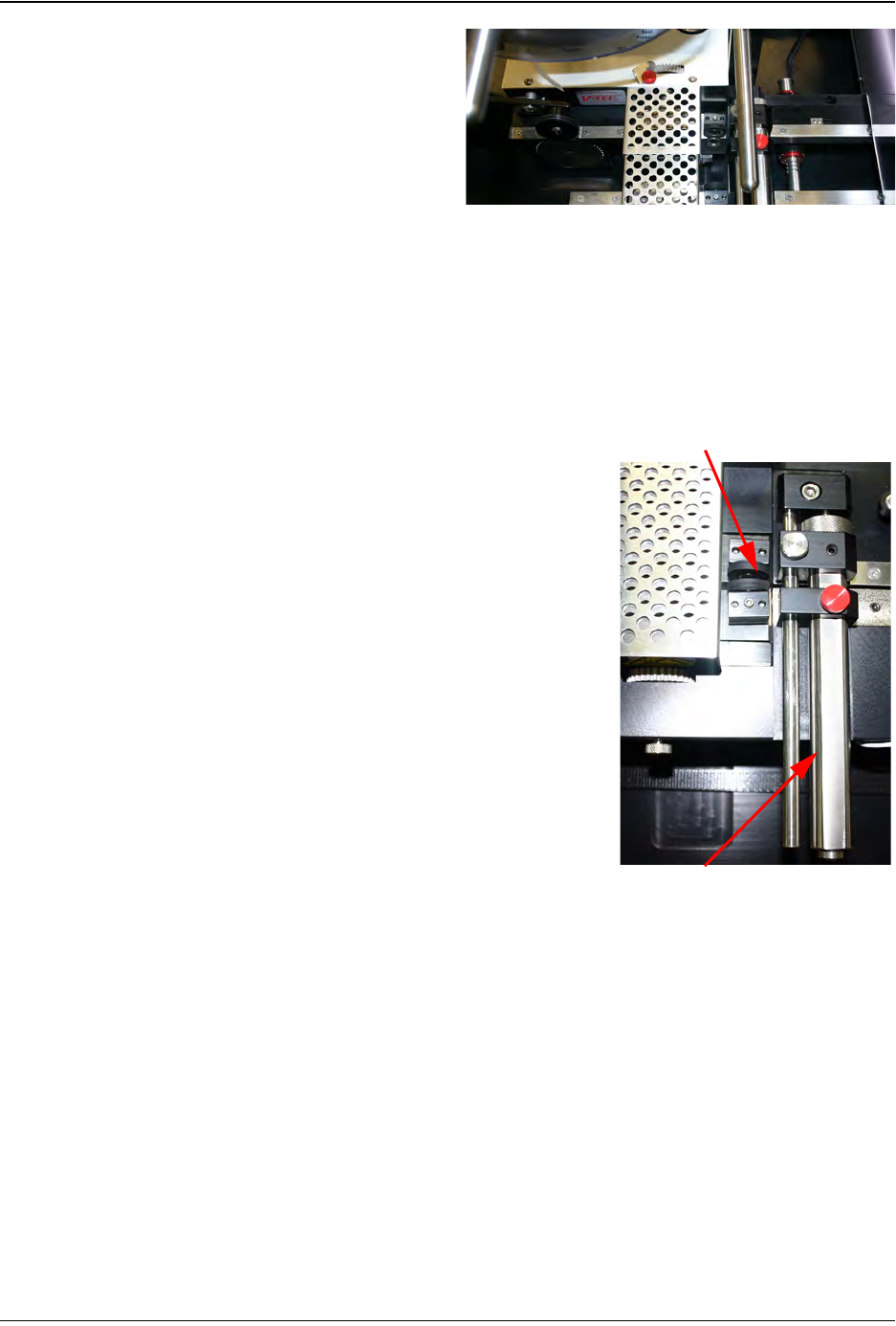
PSA Sealer
The adhesive residues should be cleaned from the sealer
assembly every 40 hours of operation.
Wipe the entire assembly using a cloth soaked in alcohol. Using
a cotton swab soaked in alcohol, clean between the sealer
wheels. Also, clean the entire surface of the black polyurethane
wheel.
Note: Do not use solvents other than alcohol when
cleaning the black polyurethane wheels.
If during the cleaning process the sealer has become com-
pletely out of adjustment, turn the small screw behind the wheel
counterclockwise approximately three turns. Slowly turn the
screw clockwise while spinning the top wheel. Stop adjusting
when the bottom wheel starts spinning with the top wheel.
Cover Tape Guide
The Cover Tape Guide may become coated with adhesive and
dirt during taping. It is important to keep the tape groove clean
for proper alignment of the cover tape.
Clean the tape groove with alcohol and a cotton swab whenever
it appears dirty. The recommended cleaning schedule is every
40 hours of operation.
Cover Tape Guide
PSA Sealer Wheels

Appendix A: Sensors
Contents
Keyence FS-N11CVP/FS-N12CP Sensor Amplifiers. . . . . . . . . . . . . . . . . .A-2
SMC ZSE30 Vacuum Sensor. . . . . . . . . . . . . . . . . . . . . . . . . . . . . . . . . . . .A-4
Appendix A: Sensors A-2
Keyence FS-N11CP & FSN12CP Sensor Amplifiers D291842.11.fm
Keyence FS-N11CP & FSN12CP Sensor Amplifiers
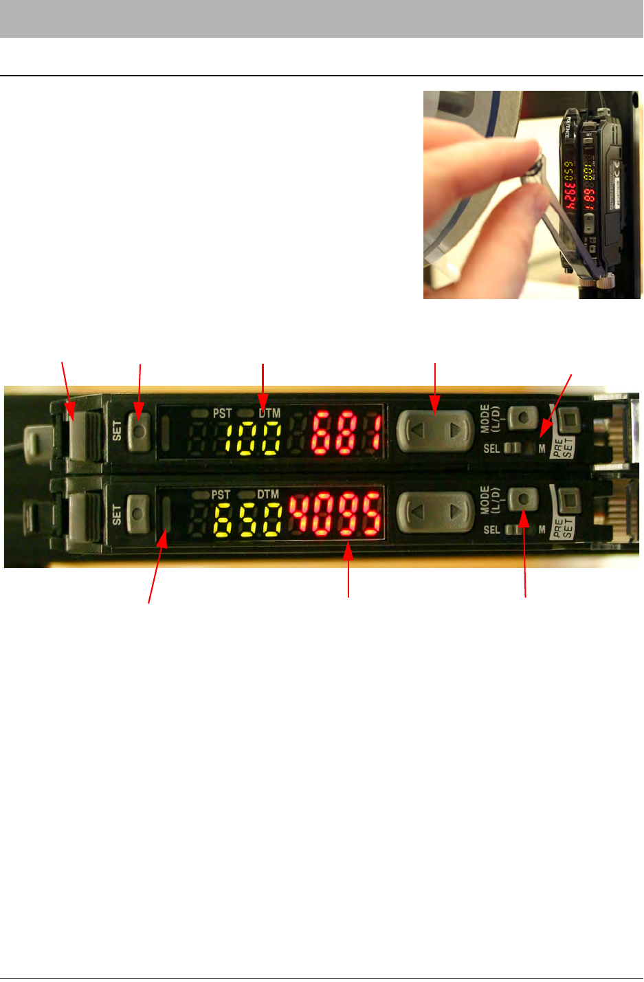
The Keyence FS-N11CP and FS-N12CP sensor amplifiers
(shown in Figure A.1 below) are used on the TM-400 Series
machines for the Low Cover Tape Sensor and the Tape Jam
Sensor. Both amplifiers are mounted on the Cover Tape
Arm. The Low Cover Tape amplifier (FS-N11CP) is located
on the left. The Tape Jam amplifier (FS-N12CP) is located
on the right.
The two amplifiers are designed to be attached electrically
and share power. Otherwise, the two units function indepen-
dently of one another.
Selecting the Output Mode
The FS-N11CP/FS-N12CP sensor-amplifiers can be set to two Output Modes: light-ON or dark-
ON. This determines under what conditions the sensor is triggered and the Operation Indicator is
lit.
In light-ON mode, the sensor will be triggered when the current value (CV) of detected light from
the emitter is higher than the preset value (PV). In dark-ON mode, the sensor is triggered when
the CV of detected light is lower than the PV. Essentially, in light-ON Output Mode the sensor
detects when an obstruction occurs (causing reflected light to increase) and in dark-ON Output
Mode the sensor detects when an obstruction is removed (causing reflected light to decrease).
1. Press the Output Selector button. The CV Indicator will display the current mode.
2. Press the Manual button within 5 seconds of having pressed the Output Selector button.
The Output Mode will be toggled.
Figure A.1
Fiber Lock Lever
Set Button Preset Value (PV) Indicator Manual Button
Output Selector
Operation Indicator Current Value (CV) indicator
Mode Button
Button