编带机说明书-含图纸ttm402.pdf - 第60页
3-18 TM-403 User’s Guide Taper Tab D292105.6a.fm The Continuous Advance button advances the tape through the Ta p e r and onto the take-up reel. It will contin ue to advance until Continuous Advance is pressed a second t…
D292105.6a.fm Taper Tab
Chapter 3: Human Machine Interface 3-17
Ta p e r Ta b
The Taper Tab allows the user to adjust taper settings by leading them through four Taper Setup
screens.
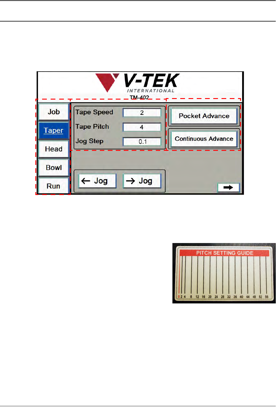
1. The first screen of the Taper Tab is shown below.
A. Press any tab in the Tab Menu to open that tab window.
B. Tape Speed is a percentage of the maximum velocity the carrier tape can be
advanced at. It can be set between 1-10.
Tape Pitch is determined by the carrier
tape selected. Use the Pitch Setting Guide
on the taper to determine the correct pitch.
Jog Step sets the distance in millimeters
the carrier tape will move forward or back-
ward each time a Jog button is pressed.
Note: The Jog Step field requires the value to be
entered in the following format: XX.XX. (i.e. 60.00).
C. The Jog buttons in the Index Settings section jog the tape forward or backward
along the Taper Track.
The Pocket Advance button advances the tape one pocket at a time. The speed
at which the tape advances is set in the Tape Speed field.
A
B
C
Taper Screen 1
3-18 TM-403 User’s Guide
Taper Tab D292105.6a.fm
The Continuous Advance button advances the tape through the Taper and onto
the take-up reel. It will continue to advance until Continuous Advance is pressed
a second time.
Note: Continuous Advance is useful for creating a trailer or loading tape at the begin-
ning of a job.
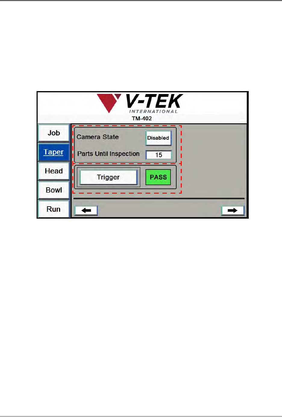
2. Pressing the right Arrow button opens the next Taper Setup screen which focuses on
Vision Setup.
A. The Camera State button toggles between Enabled and Disabled.
The Parts Until Inspection value is the number of pockets between the Place
point and the Inspection point. Begin the count at the Place position at zero, so
the Place position is not included.
B. Pressing the Trigger button triggers the 2D Camera to inspect the part which is
currently at the Inspection point. The box to the right of the Trigger button will dis-
play a green PASS message or a red FAIL message.
Note: For more detailed inspection configuration and procedures, see the Cognex
Checker User’s Guide which was included with the TM-402.
Pressing the right Arrow button opens the next Taper Setup screen.
Taper Screen 2
A
B
D292105.6a.fm Taper Tab
Chapter 3: Human Machine Interface 3-19
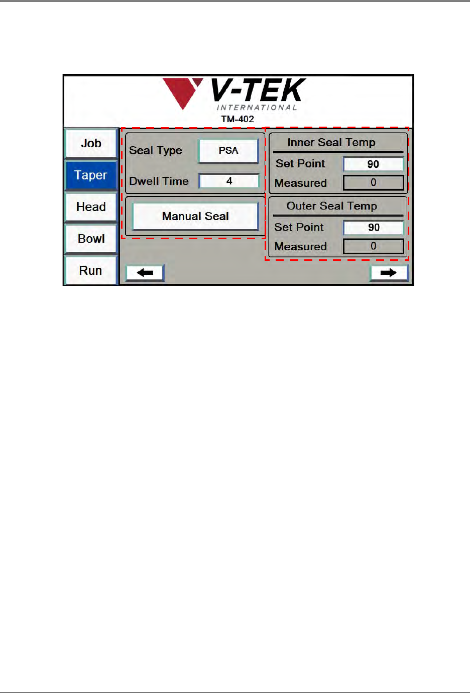
3. The third Taper Setup screen focuses on Sealer Settings. It will vary in appearance
depending on the type of sealer selected. In the example below, the selected Seal Type is
Heat.
A. The Seal Type button toggles between Heat seal and PSA seal.
The Dwell Time field is only active when heat seal is enabled. Dwell time refers to
the amount of time that the Heat Seal Shoes are in contact with the Cover Tape.
Enter the desired dwell time in milliseconds in this field.
The Manual Seal button activates the sealer to perform one seal.
B. The Set Point field allows the user to select the Heat Sealer set point, or target
temperature. Press the field to open the keypad, then enter the desired tempera-
ture in degrees Celsius.
The Measured field shows the current Heat Sealer temperature in degrees Cel-
sius.
Note: The TM-402 accommodates a wide range of carrier tapes and cover tapes. Set-
tings may vary from one tape product to another. The recommended starting point is 90°
C. The maximum recommended operating temperature is 160° C. The temperature for
each seal shoe should be increased or decreased as needed after running a peel force
test.
Taper Screen 3
A
B