编带机说明书-含图纸ttm402.pdf - 第55页
D292105.6a.fm Jo b Tab Chapter 3: Human Machine Interface 3-13 A. The Arrow keys allow the user to jog the Pick Head and Carrier T ape forward or backward in small preset increment s. This is useful for centering the Noz…
3-12 TM-403 User’s Guide
Job Tab D292105.6a.fm
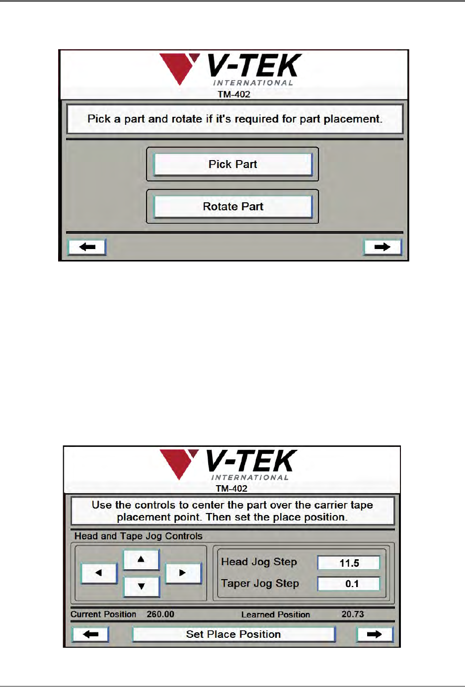
10. Press the right arrow key to move to the next screen.
A. Press Pick Part to pick a part from the nest.
B. If no rotation is required for part picking, skip this step. If part rotation is required
for picking, press Rotate Part to rotate the Nozzle 90°.
Note: Follow the directions in Chapter 4: Setup for manually adjusting the Solenoid to set
Pick Head Rotation.
11. Press the right Arrow Key to move to the next Job Wizard screen.
Job Wizard Step 7
A
B
A
C
Job Wizard Step 8
B
D292105.6a.fm Job Tab
Chapter 3: Human Machine Interface 3-13
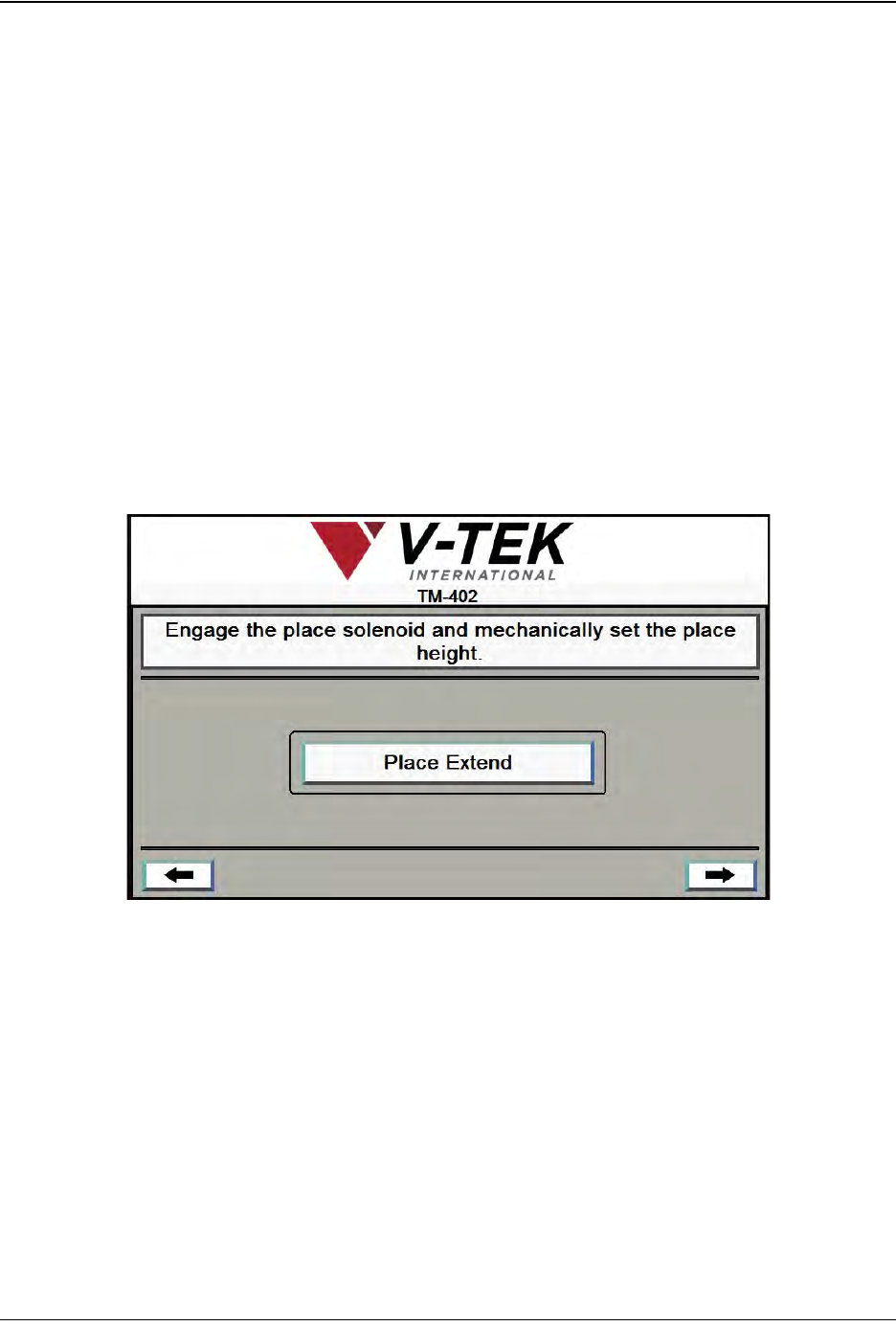
A. The Arrow keys allow the user to jog the Pick Head and Carrier Tape forward or
backward in small preset increments. This is useful for centering the Nozzle in the
pick and place positions.
The Up/Down Arrow keys move the Pick Head forward and backward.
The Left/Right Arrow keys move the tape left and right in the Taper Track.
B. Enter the value in millimeters for the Head Jog Step and Taper Jog Step fields.
C. Pressing Set Place Position saves the current Nozzle position as the Place posi-
tion for the current job and the Learned Position will update to match the Current
Position on the screen. In the bottom right corner of the screen the right Arrow
key will appear.
12. Press the right Arrow Key to move to the next Job Wizard screen.
A. Press Place Extend to lower the Nozzle to the Carrier Tape Pocket.
Note: The Place Extend button toggles between Place Extend and Place
Retract. Once Place Extend has been pressed, the button will change to
Place Retract.
Follow the directions in Chapter 4: Setup for manually adjusting the place Actuator
to set the correct Nozzle Height at the Place position.
A
Job Wizard Step 9
3-14 TM-403 User’s Guide
Job Tab D292105.6a.fm
13. Press the right Arrow Key to move to the next Job Wizard screen.
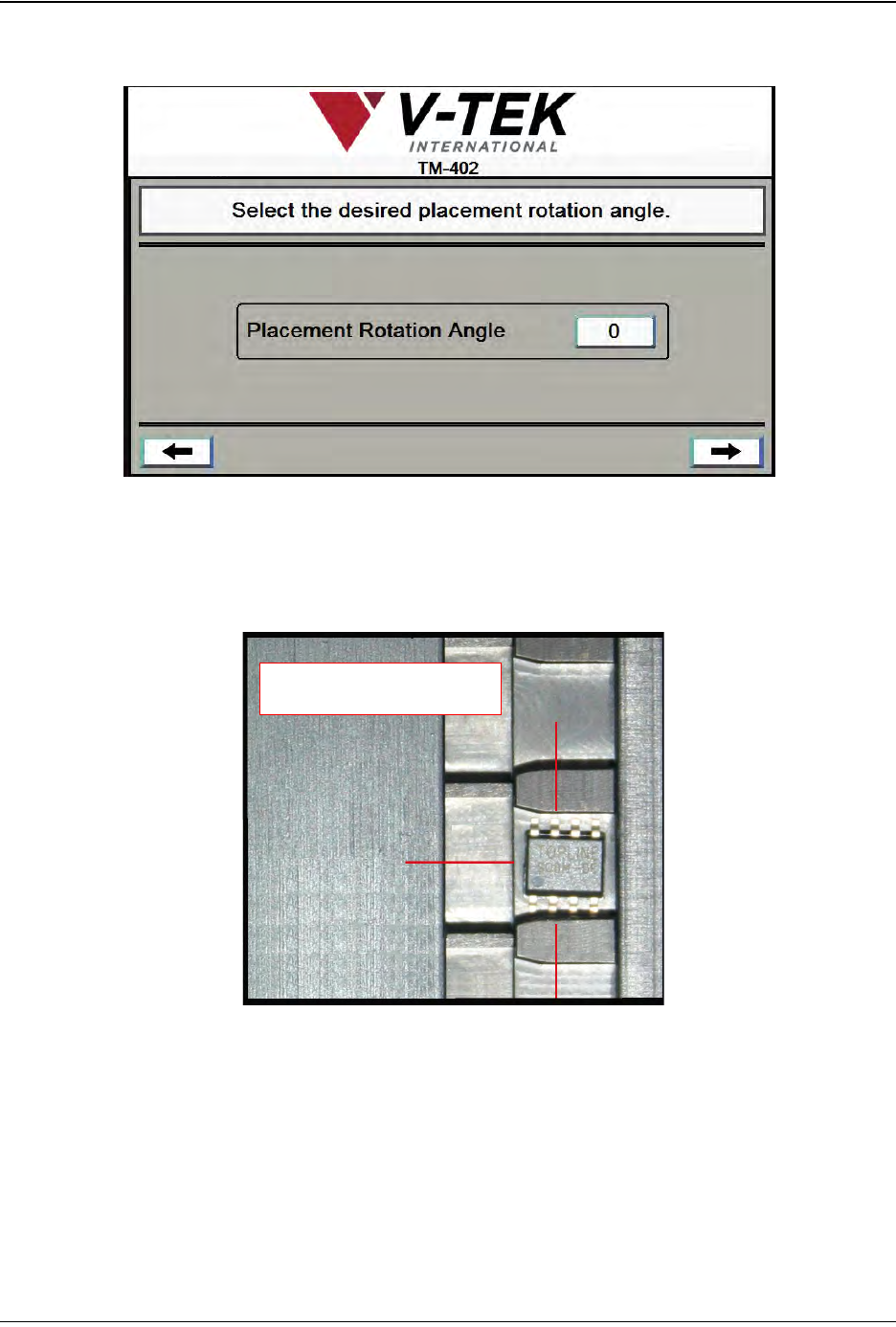
A. Enter the placement angle which was manually set in Step 10. The options are 0,
-90 and +90.
In the photo below, a part is shown at the pick position as viewed from the front of
the machine.
• If rotation is set at 0, the part will be placed in the same orientation as it was
picked.
• If rotation is set at -90, the part will be rotated 90 degrees clockwise prior to
placement.
• If rotation is set at +90, the part will be rotated 90 degrees counter-clockwise
prior to placement.
A
Job Wizard Step 10
-90
0
+90
Rotation Options