编带机说明书-含图纸ttm402.pdf - 第51页
D292105.6a.fm Jo b Tab Chapter 3: Human Machine Interface 3-9 A. T ape Pitch is determined by the carrier tape selected. Use the Pitch Setting Guide on the t aper to determine the correct pitch. Press the T ape Pitch fie…
3-8 TM-403 User’s Guide
Job Tab D292105.6a.fm
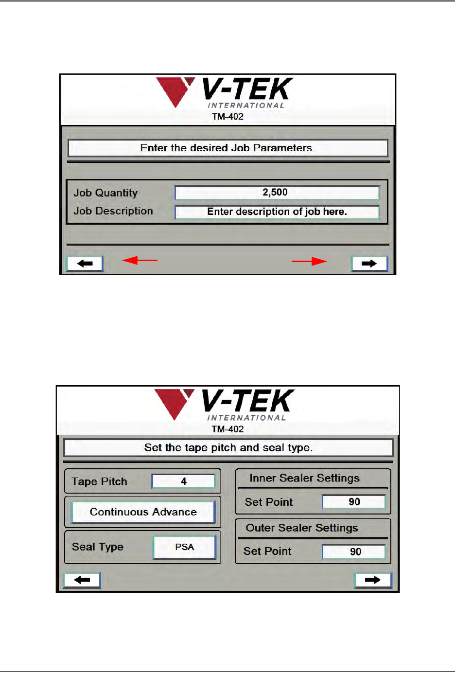
2. In the second Job Wizard screen the user enters the Quantity of parts that will be run and
a brief Description of the job. When the job parameters are set, press the right Arrow
key to move to the next Job Wizard screen.
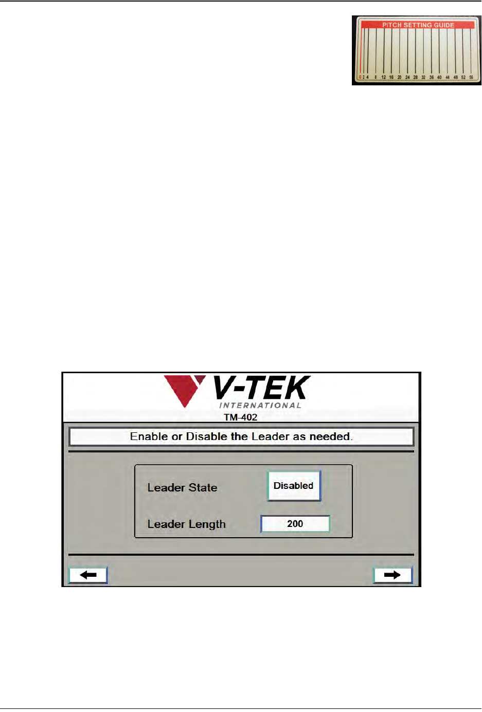
3. The third Job Wizard step sets up Taper operation.
Arrow Buttons
Job Wizard Step 2
A
C
Job Wizard Step 3
D
D
B
D292105.6a.fm Job Tab
Chapter 3: Human Machine Interface 3-9
A. Tape Pitch is determined by the carrier tape
selected. Use the Pitch Setting Guide on the taper to
determine the correct pitch. Press the Tape Pitch
field to open a keypad and type in the desired value.
B. The Continuous Advance button advances the
tape through the Taper. It will continue to advance
until Continuous Advance is pressed a second time.
C. Seal Type toggles between PSA and Heat seal, select correct seal type.
D. The Set Point fields are only active when Heat Seal is selected. These fields are
used to set the desired temperature for the Inner and Outer Sealer. Enter the cor-
rect value in both fields, then press the right Arrow Key to move to the next Job
Wizard screen.
Note: The TM-402 accommodates a wide range of carrier tapes and cover tapes. Set-
tings may vary from one tape product to another. The recommended starting point is 90°
C. The maximum recommended operating temperature is 160° C. The temperature for
each seal shoe should be increased or decreased as needed after running a peel force
test.
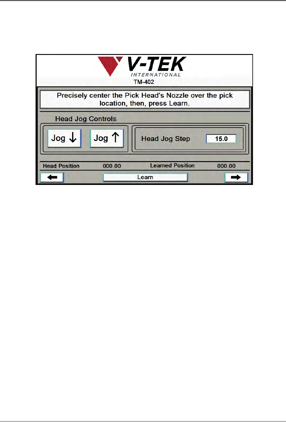
4. The fourth Job Wizard screen enables or disables the tape Leader.
A. Leader State toggles between Enabled and Disabled.
B. When the Leader State is set to Enabled, pressing the Leader Length field will
open a keypad. Type in the desired value, then press the right Arrow Key to
move to the next Job Wizard screen.
A
B
Job Wizard Step 4
3-10 TM-403 User’s Guide
Job Tab D292105.6a.fm
5. The next six Job Wizard screens are used to set the Nozzle positions at the Pick and
Place locations. The first is shown below.
A. Press the Jog buttons to move the Pick Head to the Bowl Feeder, centering it over
the Linear Track’s Nest in the pick position.
B. Adjust the Jog Step in the Head Jog Step field, if necessary.
C. Once the Pick Head is centered over the pick position, press Learn. The current
Nozzle position will be saved as the pick position for the current job and the
Learned Position will update to match the Current Position on the screen.
Job Wizard Step 5
A
B
C