编带机说明书-含图纸ttm402.pdf - 第89页
D292105.7b.fm Configure HMI Settings Chapter 4: Setup 4- 17 6. ENABLE LE ADER . a. Select Leader S tate a nd enter Leader Length in millimeters if enabled. Note: If Leader is disabled or a leader value of zero is entered…
4-16 TM-403 User’s Guide
Configure HMI Settings D292105.7b.fm
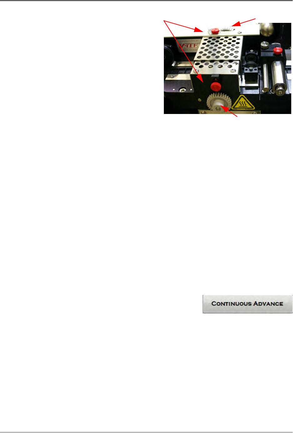
The sealer’s inside and outside
seals are independently
adjustable. If one of the seals
needs to be moved, loosen the
corresponding position lock and
turn the adjusters.
Turning the wheel counter-
clockwise will move the guide
towards the operator. Turning it
clockwise will move the guide
closer to the machine. Adjust
the Inner Seal Adjust and the
Outer Seal Adjust to the desired
position, then tighten the
Position Locks to secure them.
Note: See Chapter 6: Trouble-
shooting for sealer adjustment tips.
After the initial adjustment, run
the tape out again and observe
whether the cover tape aligns
itself satisfactorily. If it is still
misaligned, continue adjusting
the cover tape guide until it is
aligned properly.
5. CREATE TRAILER (optional)
The term “leader” and “trailer” refer to the lengths of empty carrier tape required at the
beginning (leader) and the end (trailer) of the finished reel of placed parts. Therefore,
when the reel is being taped on the TM-402, the trailer is the first length of empty carrier
tape run before the first part is taped and the leader is the length of empty carrier tape run
after the last part is taped.
a. There are no HMI controls for creating a
Trailer. If a Trailer is desired, simply open
the HMI Taper Tab and press Continuous
Advance at the beginning of the reel and
run out sealed empty pockets until the
desired trailer length is reached.
b. Press the right Arrow key to move to the
next screen and configure leader creation.
Inner Seal Adjust
Outer Seal Adjust
Position Locks
Step 6:
Setup HMI
TA P ER
D292105.7b.fm Configure HMI Settings
Chapter 4: Setup 4- 17
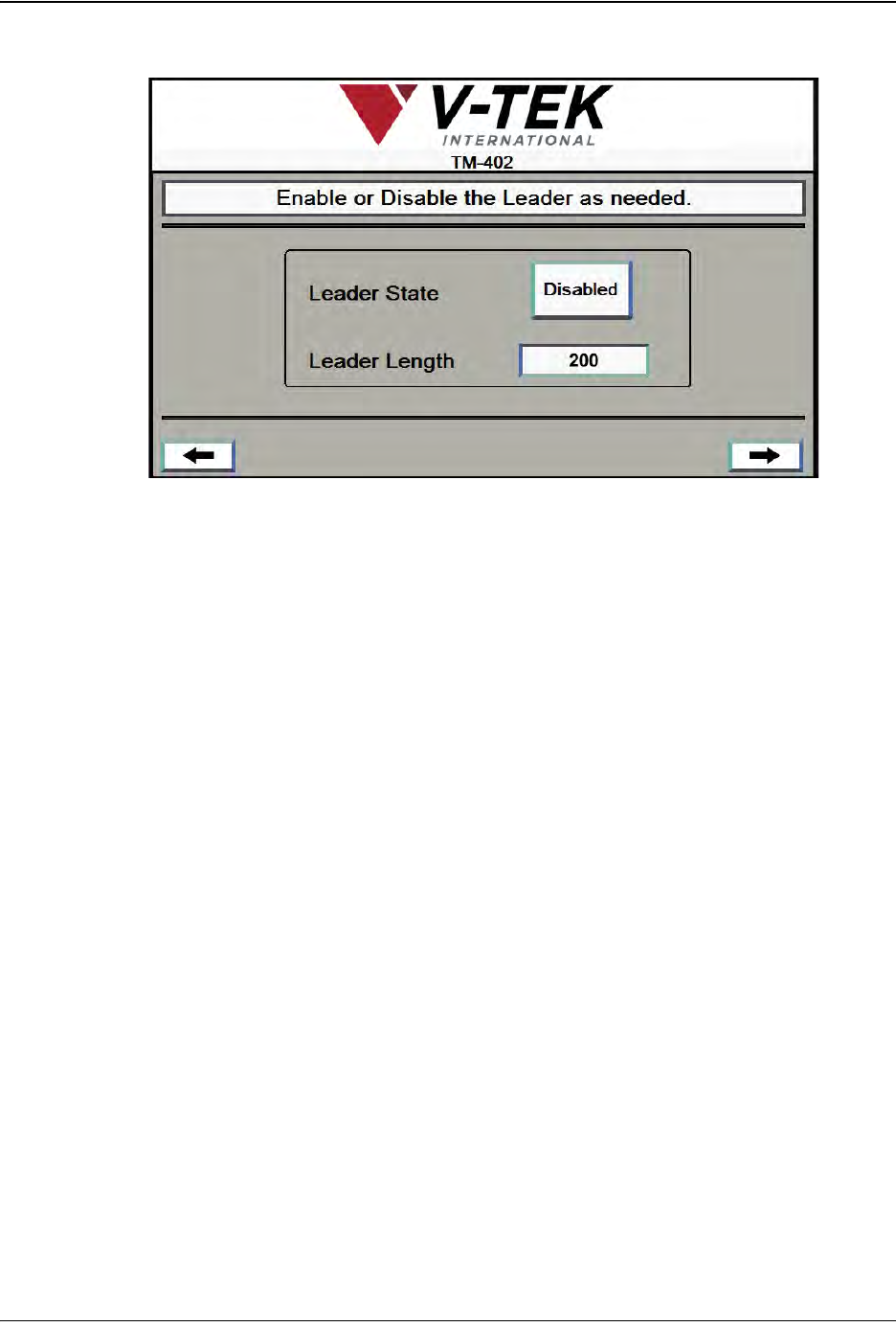
6. ENABLE LEADER.
a. Select Leader State and enter Leader Length in millimeters if enabled.
Note: If Leader is disabled or a leader value of zero is entered, the Taper will
automatically advance the last part until it reaches the cut point. If a leader value
is entered, it will move the last placed part that distance beyond the cut point.
b. Press the right Arrow key to move to the next screen.
Step 6:
Setup HMI
TA P ER
4-18 TM-403 User’s Guide
Configure HMI Settings D292105.7b.fm
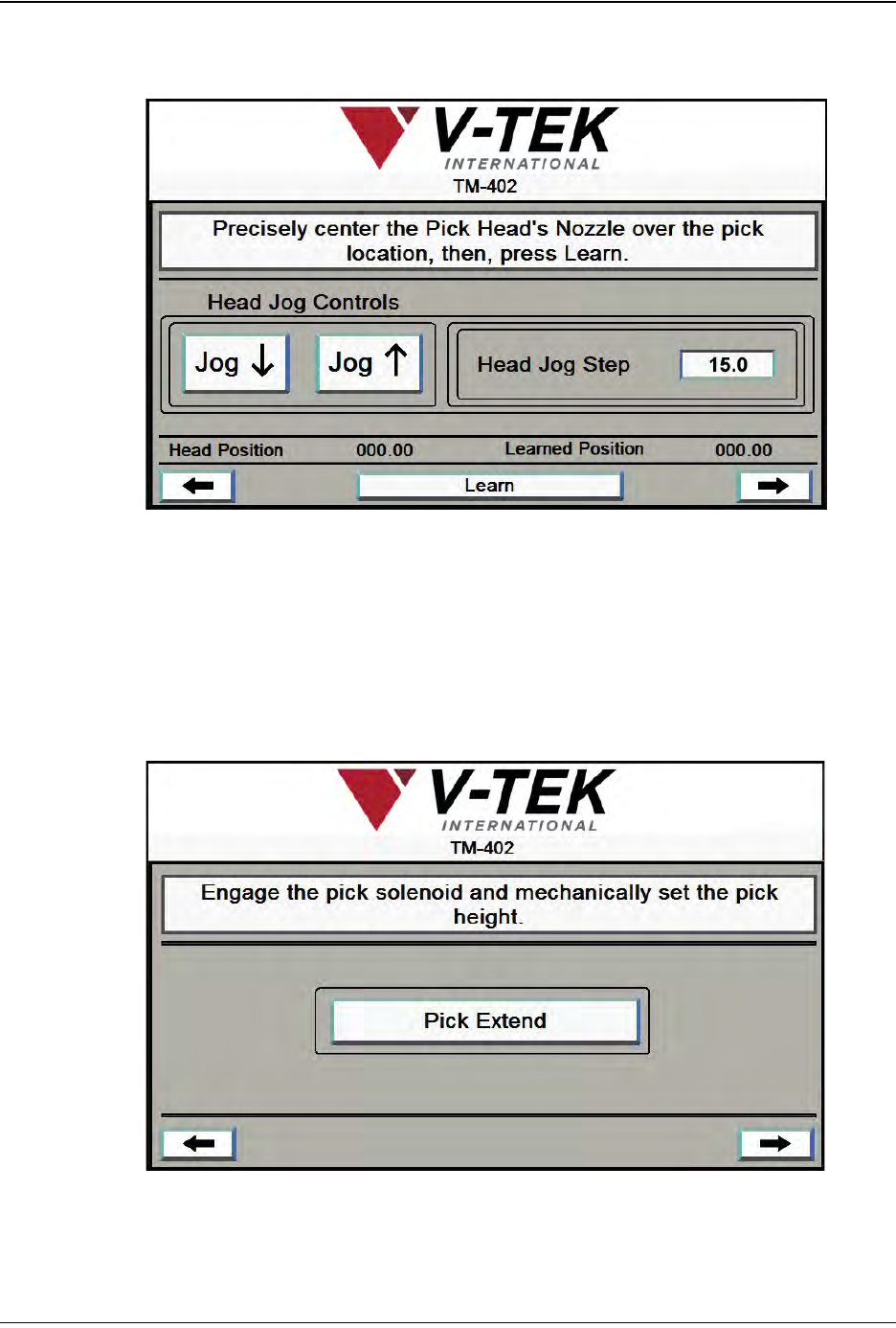
7. PICK HEAD SETUP The next seven Job Wizard screens are used to set the pick
and place positions.
a. Press the Jog buttons or the Jog buttons on top of the Sealer enclosure to
move the Pick Head to the Bowl Feeder, centering it over the Nest in the pick
position.
b. Press Learn. The Learned Position will now match the Current Position and
the Learn button will turn green and update to read Learned.
c. Press the right Arrow to move to the next Job Wizard screen. .
Step 6:
Setup HMI
PICK
HEAD
A
B
C