编带机说明书-含图纸ttm402.pdf - 第81页
D292105.7b.fm Taper Setup Chapter 4: Setup 4- 9 Ta p e r S e t u p Loading T ape The T aper mu st be loaded with carrier and cover tapes and configured for operation. Begin by preparing the T aper , then move t o the HMI…
4-8 TM-403 User’s Guide
Nozzle Installation D292105.7b.fm
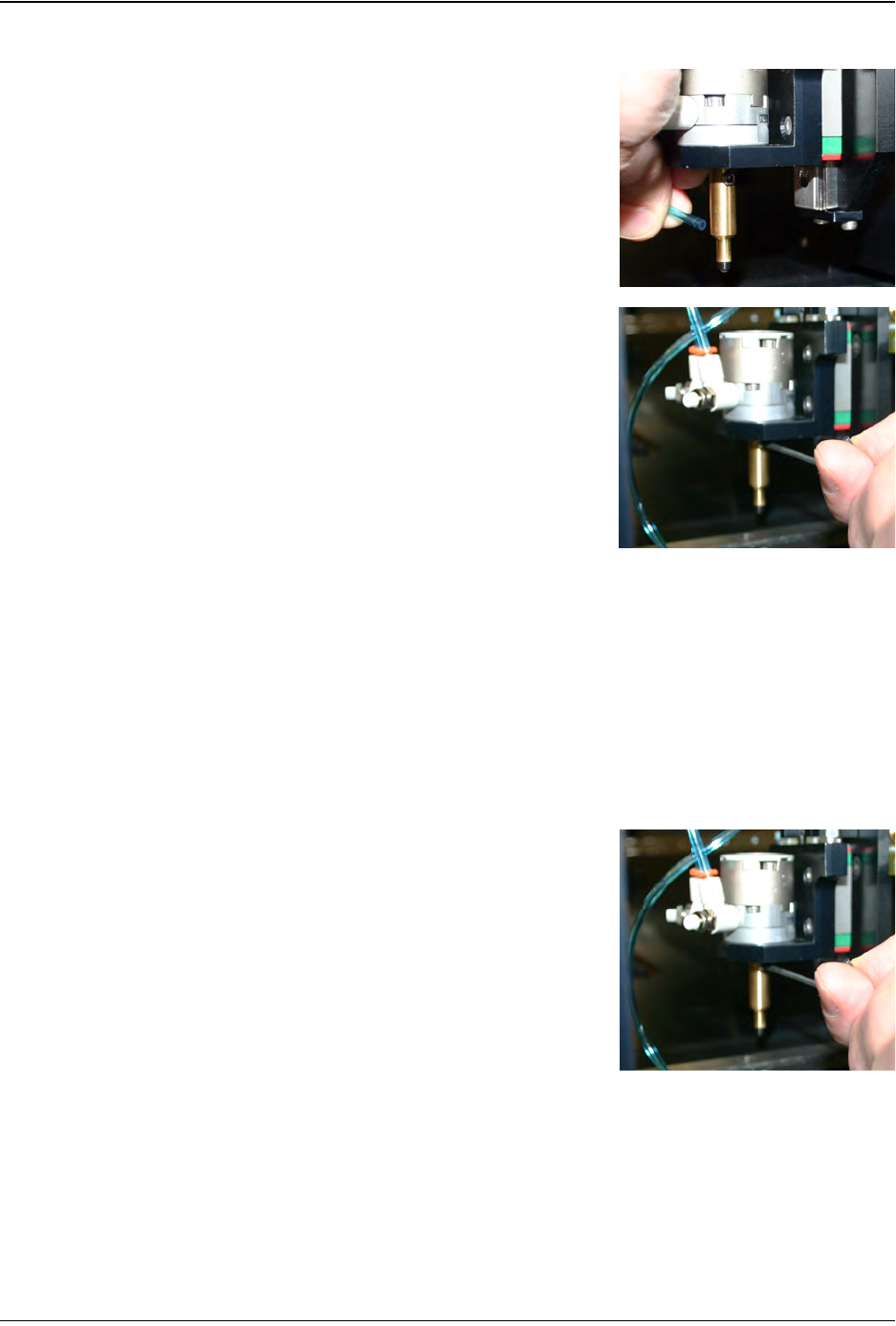
Installing Nozzle & Nozzle Tip
1. Move the Pick & Place Head to the Place position
so it is easily accessible from the front. .
2. Remove the air line from the Nozzle Shank, sup-
porting the Nozzle with one hand while gently pull-
ing the tube off the Nozzle Barb.
3. Using a 2mm Hex wrench, loosen the set screw
that retains the Nozzle Shaft.
4. Slide the Nozzle Shank down and remove it from
the Pick & Place Assembly. Store the unused
Nozzle Shank and Nozzle Cup in the Spare Parts
Kit.
5. Select the correct Nozzle Shank and Nozzle Cup
for the part that will be run. Press the Nozzle Cup
onto the Nozzle Shaft.
6. Insert the Nozzle Shank into the Actuator Shaft in
the Pick & Place Assembly.
Note: When positioning the Nozzle Shank,
push it all the way up to the Actuator Shaft,
then pull it back slightly (about 1mm) so the
body of the Nozzle Shank doesn’t rub the body
of the Actuator.
7. Using a 2mm Hex wrench, tighten the set screw to
retain the Nozzle Shaft..
8. Re-attach the air line to the Nozzle Barb.
Step 4:
Nozzle
Installation
INSTALL
NOZZLE
D292105.7b.fm Taper Setup
Chapter 4: Setup 4- 9
Ta p e r S e t u p
Loading Tape
The Taper must be loaded with carrier and cover tapes and configured for operation.
Begin by preparing the Taper, then move to the HMI to adjust settings. (Step 7)
Load Carrier Tape
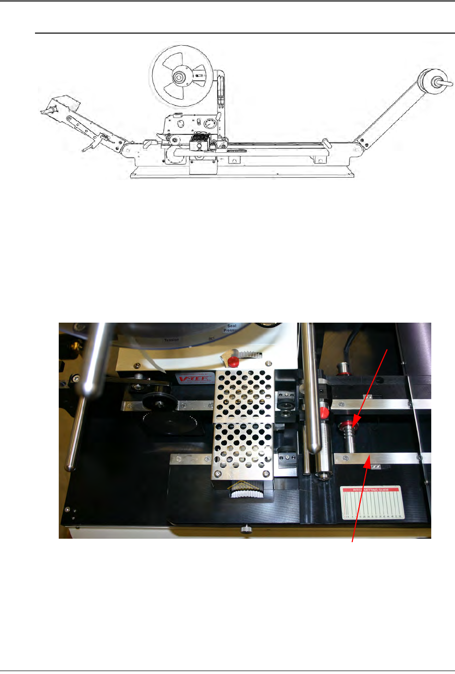
1. Check that the taper is set at the correct width for the carrier tape. If not, push or
pull the outer track in or out as needed, sliding it on the Detent Shafts until it is at
the required width.
3. Once the track is adjusted, use a strip of the carrier tape as a test to determine if
the setting is correct. The carrier tape should slide through freely, but without
excess play back and forth. Tighten the set screws down again to secure the track
into place.
Step 5:
Setup
Ta p e r
Step 5:
Setup
Ta p e r
CARRIER
TA P E
Detent Shaft
Outer Track
4-10 TM-403 User’s Guide
Taper Setup D292105.7b.fm
4. Mount the bulk carrier tape reel on the spindle, ensuring that there is sufficient tape
for the batch to be run.The carrier tape should roll off to the left, unwinding from the
top so it will feed right side up into the carrier tape channel underneath the Pick
Head Enclosure.
The sprocket holes of the carrier tape are on the inside for tape widths less than
32mm. Tapes wider than 32mm have holes on both sides.
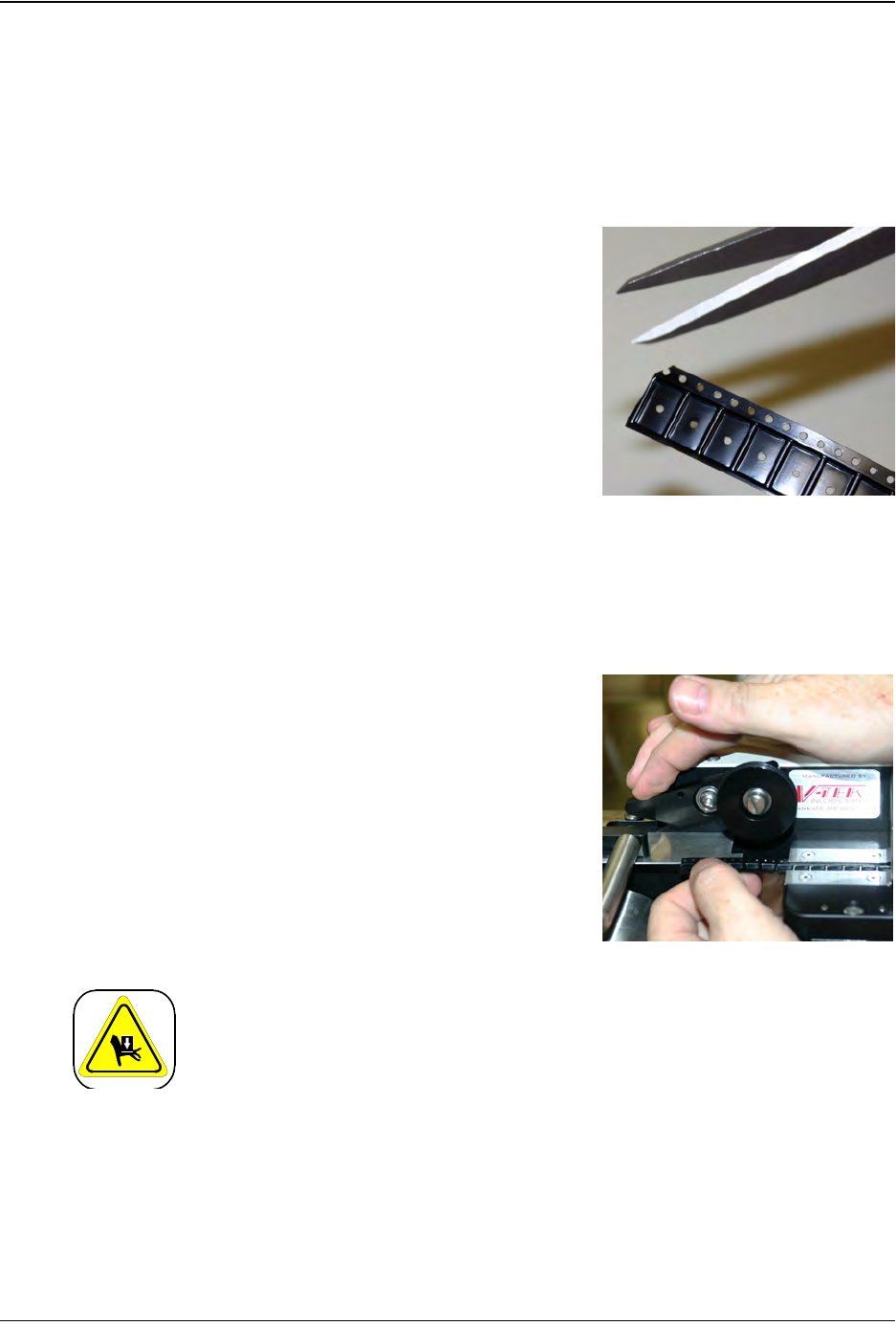
5. Trim the end of the carrier tape, cutting
between two pockets with a sharp scissors so
the edge is cleanly cut. Cut the edge of the
tape again, cutting through a sprocket hole at
a 45° angle so the tape feeds easily.
6. Guide the carrier tape under the Carrier Tape
Guide and then feed it through the carrier
tape channel under the taper.
Note: A sharp instrument, such as a pair of
tweezers may aid in guiding the carrier tape
into the loading track.
7. Continue to guide the carrier tape forward
through the loading track and the sealer until
it reaches the sprocket.
8. Lift the idler wheel and place the carrier tape
onto the sprocket so that the holes engage
the teeth. Release the idler wheel so that it is
secured in place.
Mechanical Hazard!
Do not attempt to activate the sprocket while tape is being routed
through the sealer. Pinching or entrapment may occur if safety precau-
tions are not observed.