编带机说明书-含图纸ttm402.pdf - 第79页
D292105.7b.fm Nozzle Installation Chapter 4: Setup 4- 7 Nozzle Installation The TM-402’ s is shipped with the following nozzles and nozzle tips: • (1) Quad Nozzle Shank (Part # 267090) • (1) Small Precision T ool (SPT) N…
4-6 TM-403 User’s Guide
Load the Bowl Feeder D292105.7b.fm
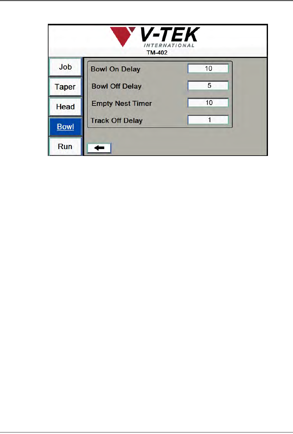
7. Click the right Arrow to move to the second Bowl Setup Screen..
8. Set the desired times in milliseconds for Bowl On Delay, Bowl Off Delay, Empty
Nest Timer and Track Off Delay.
The Bowl Feeder is now ready to operate. Feeder settings will be configured later
in this chapter in the Job Wizard section.
D292105.7b.fm Nozzle Installation
Chapter 4: Setup 4- 7
Nozzle Installation
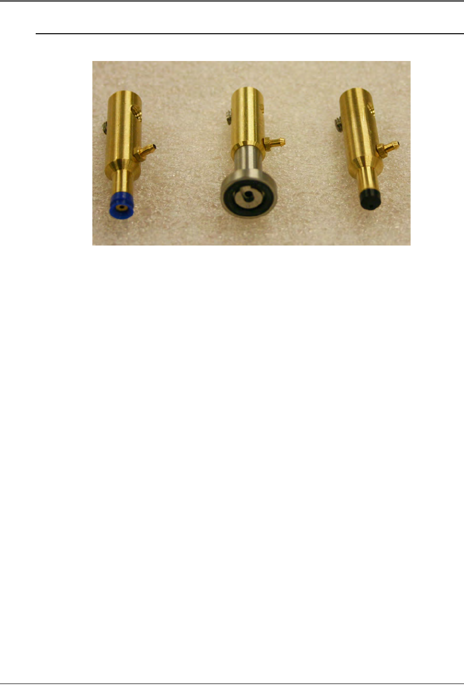
The TM-402’s is shipped with the following nozzles and nozzle tips:
• (1) Quad Nozzle Shank (Part # 267090)
• (1) Small Precision Tool (SPT) Nozzle Shank (Part # 267091)
• (1) Convum Nozzle Shank (Part # 267008)
• (1) Large Quad Vacuum Cup (Part # 201297)
• (1) Medium Quad Vacuum Cup (Part # 201298)
• (1) Small Quad Vacuum Cup (Part # 201299)
• (1) SPT Vacuum Cup (Part # 201271)
• (1) Convum Vacuum Cup (Part # 201207)
• (2) Nozzle O-Rings (Part # 212025)
Note: Nozzle Tips are available in a wide range of sizes and style. See the Sug-
gested Spare Parts List in the back of this User’s Guide for more details. Contact
V-TEK Service for information on ordering additional Nozzle Tips.
Selecting the Correct Nozzle & Nozzle Tip
To achieve the best picking results, select the largest cup size the part can accommo-
date. Maximizing the cup size gives the vacuum access to more surface area which
increases its pick-up capability. The goal is to use a nozzle cup that is just slightly smaller
than the part being picked.
The Convum bellows-style cups have a flexible flange that are useful for picking irregular
or heavy parts.
Step 4:
Nozzle
Installation
SELECT
NOZZLE
Convum Quad SPT
4-8 TM-403 User’s Guide
Nozzle Installation D292105.7b.fm
Installing Nozzle & Nozzle Tip
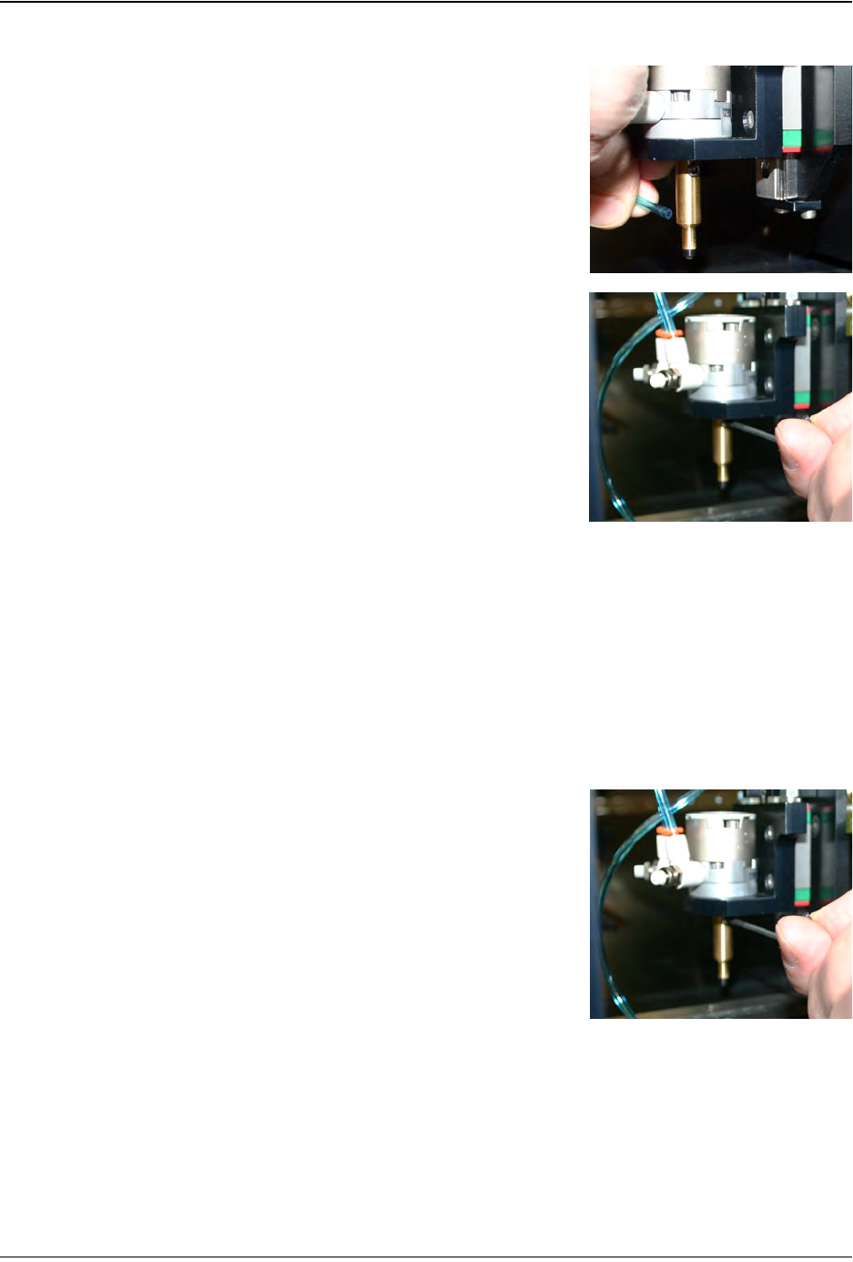
1. Move the Pick & Place Head to the Place position
so it is easily accessible from the front. .
2. Remove the air line from the Nozzle Shank, sup-
porting the Nozzle with one hand while gently pull-
ing the tube off the Nozzle Barb.
3. Using a 2mm Hex wrench, loosen the set screw
that retains the Nozzle Shaft.
4. Slide the Nozzle Shank down and remove it from
the Pick & Place Assembly. Store the unused
Nozzle Shank and Nozzle Cup in the Spare Parts
Kit.
5. Select the correct Nozzle Shank and Nozzle Cup
for the part that will be run. Press the Nozzle Cup
onto the Nozzle Shaft.
6. Insert the Nozzle Shank into the Actuator Shaft in
the Pick & Place Assembly.
Note: When positioning the Nozzle Shank,
push it all the way up to the Actuator Shaft,
then pull it back slightly (about 1mm) so the
body of the Nozzle Shank doesn’t rub the body
of the Actuator.
7. Using a 2mm Hex wrench, tighten the set screw to
retain the Nozzle Shaft..
8. Re-attach the air line to the Nozzle Barb.
Step 4:
Nozzle
Installation
INSTALL
NOZZLE