编带机说明书-含图纸ttm402.pdf - 第98页
4-26 TM-403 User’s Guide Test Seal D292105.7b.fm corresponding position lock and turn the adjusters. T urning the wheel counter-clockwise will move the guide towards the operator . T urning it clockwise will move the gui…
D292105.7b.fm Test Seal
Chapter 4: Setup 4- 25
Te s t S e a l
Perform a Seal Test to ensure a good seal. Adjust Sealer settings in the HMI Taper tab as
necessary.
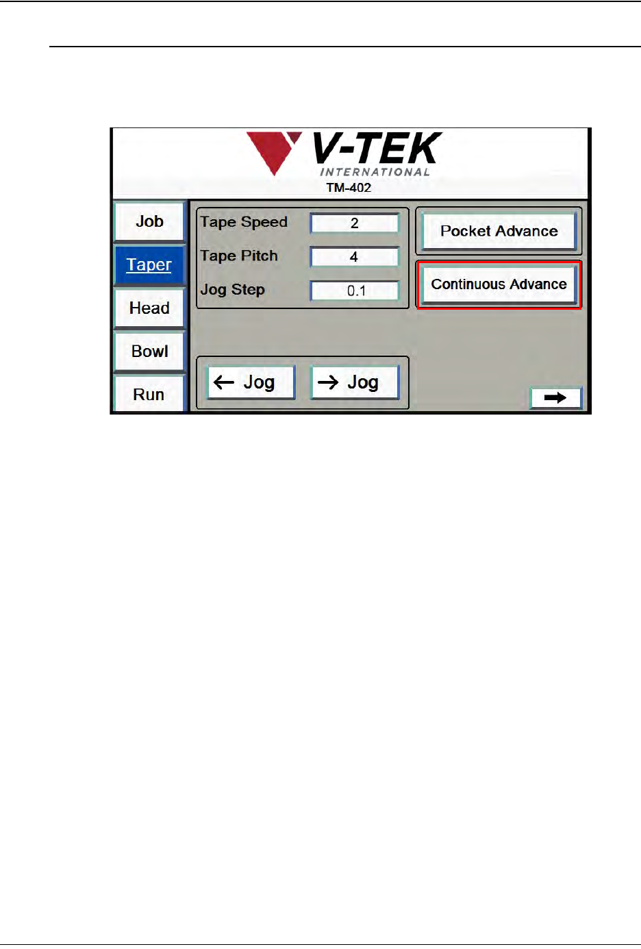
1. Run the tape through the taping module by pressing the Continuous Advance
button in the HMI Taper Tab.
2. As the seal is occurring, watch the alignment of the cover tape with the carrier
tape. The cover tape should run exactly in the groove of the cover tape guide and
the seal should appear as a solid, consistent line. If the seal width is incorrect, stop
the Taper by pressing the Continuous Advance button again.
3. Adjust the seal positions as necessary. The sealer’s inside and outside seals are
independently adjustable. If one of the seals needs to be moved, loosen the
Step 7:
Seal Test
Taper Screen 1
4-26 TM-403 User’s Guide
Test Seal D292105.7b.fm
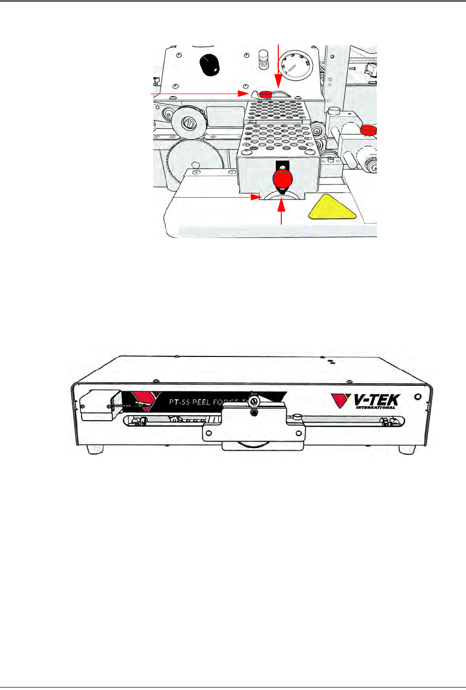
corresponding position lock and turn the adjusters.
Turning the wheel counter-clockwise will move the guide towards the operator.
Turning it clockwise will move the guide closer to the machine. Adjust the Inner
Seal Adjust and the Outer Seal Adjust to the desired position, then tighten the
Position Locks to secure them.
4. Perform a Seal Test.
The V-TEK PT-55 Peel Force Tester is pictured above. (Sold separately.)
Proceed to Chapter 5: Vision Setup to configure the Vision System for operation.
Inner Seal Adjust
Outer Seal Adjust
Position Lock
Position Lock

Chapter 5: Vision Setup
Contents
Quick Start: Vision Setup . . . . . . . . . . . . . . . . . . . . . . . . . . . . . . . . . . . . .5-2
Connect Vision. . . . . . . . . . . . . . . . . . . . . . . . . . . . . . . . . . . . . . . . . . . . . .5-3
Setup HMI . . . . . . . . . . . . . . . . . . . . . . . . . . . . . . . . . . . . . . . . . . . . . . . . . . . . 5-3
Connect Computer. . . . . . . . . . . . . . . . . . . . . . . . . . . . . . . . . . . . . . . . . . . . . . 5-5
Connect Keyence Monitor . . . . . . . . . . . . . . . . . . . . . . . . . . . . . . . . . . . . . . . . 5-9
Configure Inspection. . . . . . . . . . . . . . . . . . . . . . . . . . . . . . . . . . . . . . . . .5-10
Configure Computer. . . . . . . . . . . . . . . . . . . . . . . . . . . . . . . . . . . . . . . . . . . . . 5-10
Configure Keyence Monitor . . . . . . . . . . . . . . . . . . . . . . . . . . . . . . . . . . . . . . . 5-28